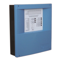
Digital fire detection control panel
COMPACT LYON
20
FIRE PRETECTION MANUFACTURER
Ctra. de Molins de Rei a Rubí, Km. 8,4 - 08191 RUBÍ (Barcelona) ESPAÑA.
Tlf.: +34 935 862 690 - Fax:+34 936 999 261 - cofem@cofem.com - www.cofem.com
1.5.4- Repeaters
1.5.4.1- Installation
The repeater must be fixed on a vertical wall face. The side slots must be left free for heat to escape.
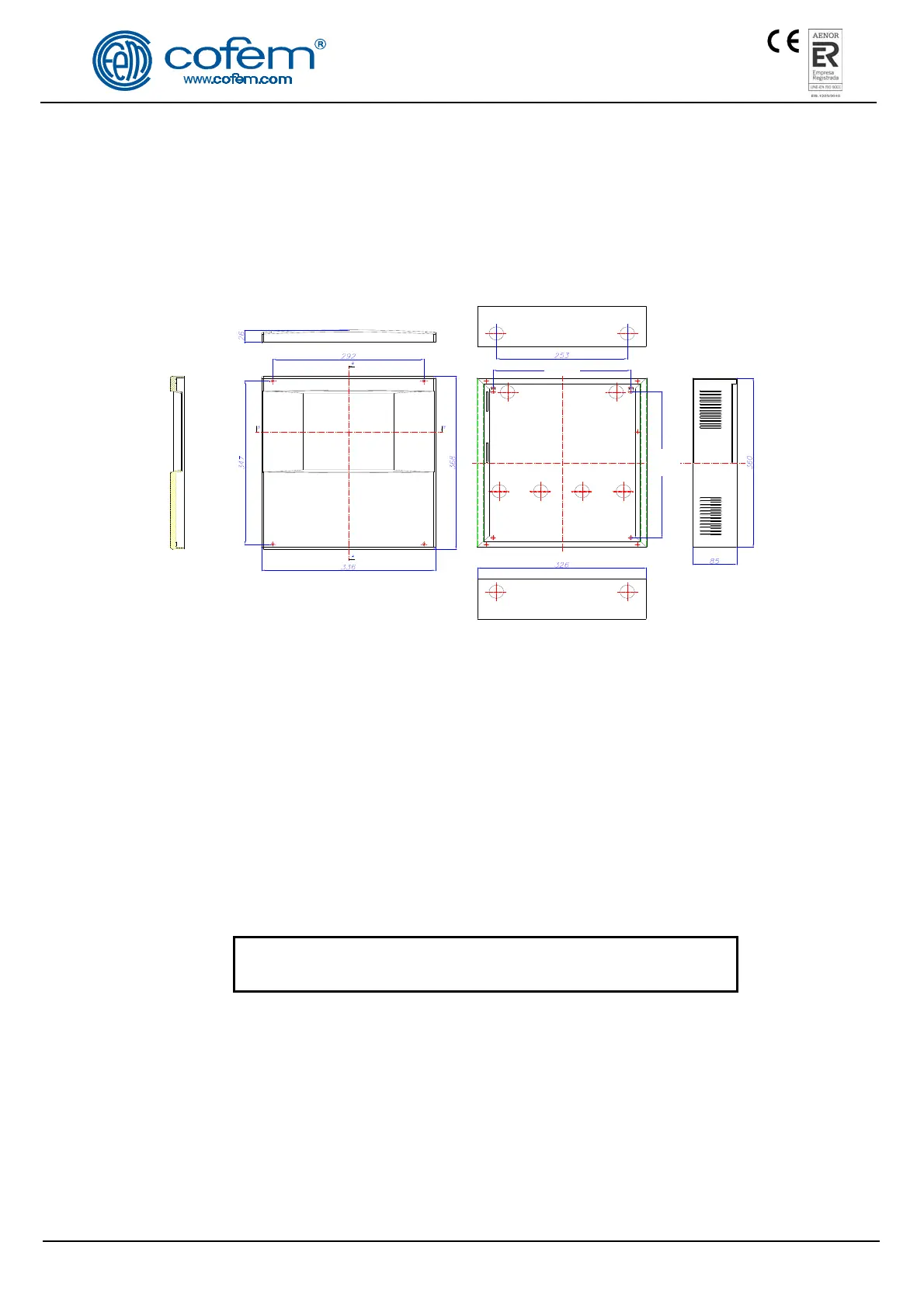
The dimensions and the pre-drilled holes for cable entry are shown in the following diagram.
Figure 10. Compact Lyon repeater box
The COMPACT LYON control panel allows connecting up to 15 repeaters. For this, a 4-wire
connection of 1.5 mm
2
wires (two for power supply and two for RS485 communication) must be used.
The two wires for the RS485 line must be connected from the connector indicated as REPETIDOR at
the Control Panel, with each connector of the repeaters indicated as REPETIDOR on the label.
The two power supply wires must be connected from the 30 V output of the Control Panel power
supply, with the connector indicated with 30 VDC in each repeater. Figure 11 shows this wiring diagram.
It can be used the Compact Lyon control panel’s power supply 30V output for 1 repeater. In
other cases (from 2 to 15 repeaters), it must be used the 30 V output of an auxiliary power supply
(FAE).
For repeaters connection, both the communication and 30V power supply cables must be 2 x 1.5 mm
HALOGEN-FREE SCREENED BRAIDED CABLE, with a maximum cable length of 1200 metres.
DISCONNECT the 230V MAINS voltage and the BATTERIES
before handling the inside of the control panel or the repeaters.
1.5.4.2- Operation and Configuration
The repeaters display all the information about alarms, disconnections, relay actuations and faults.
Once the repeaters have been connected, they must then be configured in the control panel by entering the
number of each repeater to be configured. To do this, follow this sequence in the control panel: Menu
(access code 27) 4- System configuration (access code 9000) 8- Communications 1- Repeater
network 2- Configure repeaters.
 Loading...