Do you have a question about the Cofem LYON and is the answer not in the manual?
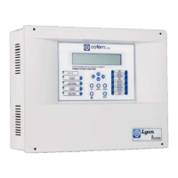
Provides an overview of the analogue fire detection control panel and its capabilities.
Explains how the analogue detection system measures, processes, and transmits data.
Lists the key features, capabilities, and specifications of the control panel.
Details the physical components and internal modules that make up the control panel.
Defines the maximum number of devices that can be connected to a single detection loop.
Describes various types of analogue sensors used in fire detection systems.
Details the functionality, operation, and specifications of analogue smoke sensors.
Explains the operation, features, and specifications of the analogue temperature sensor.
Covers the multi-sensor device detecting smoke, temperature, and CO.
Describes the analogue manual call point for manual fire alarm activation.
Introduces various modules that extend the system's capabilities and functions.
Module for interfacing conventional detectors with the analogue system.
Module with one relay output for control functions and system signaling.
Module with two independent relay outputs for control and system signaling.
Module for signaling external systems via dry contacts.
Protects the loop by isolating sections with faults.
Devices providing audible and visual alarms for fire events.
Module with one relay output and one technical signal input.
Devices for remote display and interaction with the system status.
Instructions for physically mounting and connecting repeaters.
How to operate, configure, and manage repeater settings.
Information on how to network multiple control panels together.
Steps for physically installing control panels in a network configuration.
How to configure and operate networked control panels.
Lists optional accessories available for enhancing system functionality.
Connecting and using a standard PC keyboard for system programming.
Requirements and connection details for PC-based programming software.
Instructions for physically installing the control panel unit.
Details on how to connect the various components of the analogue system.
Explains the power supply requirements and connection methods.
Describes the hardware responsible for driving and managing detection loops.
Details auxiliary power outputs and battery charging/monitoring.
Lists and describes the main hardware components of the fire detection system.
Information on connecting and managing system batteries for power continuity.
Illustrates the general wiring diagram for a typical detection loop.
Explains wiring for sounders and relay-controlled devices.
Wiring instructions for specific internal two-tone 24V sounders.
Wiring instructions for the non-flashing internal 24V sounder.
Wiring instructions for the flashing internal 24V sounder.
Wiring instructions for connecting the external 24V alarm box.
Lists optional accessories for the fire detection system.
Connecting and using a PC keyboard for system programming.
Requirements and connection details for PC-based programming software.
Details the front panel controls, LEDs, and screen layout.
Explains the functionality of each key on the control panel keypad.
Describes the status indicated by the LEDs on the front panel.
Information about the alphanumeric display and its content.
Defines the different user access levels and their permissions.
Basic functions accessible at Level 1 for system monitoring.
Steps for starting up and initializing the control panel.
Functions accessible with the Level 2 maintenance access code.
Procedure for entering the Level 2 access code to unlock functions.
Keypad functions available to Level 2 users.
Procedure for resetting system events and alarms.
Viewing real-time sensor readings and historical data.
Managing the activation and deactivation of logical relays.
Managing the activation and deactivation of general relays.
Accessing the main system configuration settings.
Managing the status of devices and zones within the system.
Procedure for executing a comprehensive system test.
Customizing the welcome message displayed on the control panel.
Performing a full system reset to factory defaults.
Viewing past system events, alarms, faults, and relay activities.
Advanced system configuration settings accessible at Level 3.
Entering the Level 3 access code for system configuration.
Assigning descriptive labels to system elements for identification.
Main menu for accessing various system configuration options.
Settings related to loop setup, element detection, and sensitivity.
Configuring relay behavior, activation modes, and delays.
Setting up alarm zones for faster incident location and reporting.
Adjusting the sensitivity levels of various system sensors.
Setting up additional passwords for access levels.
Setting up automatic evacuation sequences and delays.
Configuring additional delays for relay activations.
Configuring zones for immediate relay activation upon alarm.
Transmitting configured zone information to repeaters.
Setting the system's date and time for accurate logging.
Configuring different relay operations for day/night schedules.
Switching between test and normal operating modes.
Controlling the illumination of element LEDs for specific modes.
Selecting the system's display language.
Managing network and communication settings for panels and repeaters.
Configuring the behavior and activation of the sounder stop function.
Pre-installation checks and requirements for the fire detection system.
Details on connecting the main power supply and battery backup.
Steps for connecting and configuring detection loops and relays.
Troubleshooting common faults encountered during control panel startup.
Diagnosing and resolving issues related to the power supply system.
Troubleshooting problems related to the detection loops.
Addresses various other fault conditions and their solutions.
Introduction to the LYON system's capabilities and purpose.
Visual guide to the control panel's front interface, keys, and LEDs.
Explains the causes of the buzzer and how to silence it.
How to investigate and understand system incidents displayed on the panel.
Procedure for initiating an evacuation via the control panel.
How to silence audible alarms when required.
Procedure for clearing system events, alarms, and faults.
Overview of system elements and steps for configuring them.
Accessing system functions via keypad and understanding access levels.
Steps for configuring individual points within a detection loop.
Main menu for programming system parameters and settings.
Accessing various system configuration submenus.
Settings related to loop parameters, element detection, and sensitivity.
Detailed steps for configuring loop elements and their properties.
Assigning unique numbers to points within a loop for identification.
Verifying the correctness of programmed settings and element assignments.
Defining alarm zones for improved incident location and management.
Procedures for replacing a faulty or removed loop element.
| Power supply | 230V AC |
|---|---|
| Batteries | 2 x 12V 7Ah |
| Display | LCD |
| Communication | RS-485 |
| Loops | 2 |
| Auxiliary outputs | 2 |