Do you have a question about the Cofem COMPACT LYON and is the answer not in the manual?
General overview of the Compact Lyon digital fire detection system.
Explains how the digital detection system measures and transmits data.
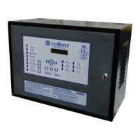
Lists key features and capabilities of the control panel.
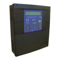
Details the physical components of the control panel unit.
Lists and describes devices connected externally to the panel.
Details types of analogue sensors used for detection.
Description of smoke detection sensors like A30XHA and A30XHA-S.
Description of the analogue temperature sensor A30XTA.
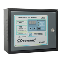
Description of the A30XHTCO multi-sensor.
Description of the analogue manual call point PUCAY.
Details various functional modules for the system.
Module for connecting conventional detectors and call points.
Module with two relay outputs for activation.
Module with one relay output for activation.
Module for inputting technical signals from other systems.
Device to isolate loop sections with short-circuit failures.
Devices for audible and visual alarms.
Module with one relay output and one technical signal input.
Devices for extending the system's reach and displaying information.
Describes networking capabilities of control panels.
Optional items for enhancing system functionality.
External keyboard for programming and configuration.
Software for programming and configuration of the control panel.
Instructions on physically mounting the control panel unit.
Guidelines for connecting system components and modules.
Details on connecting the main 230V power supply.
Information on the loop driver components and connections.
Description of auxiliary power outputs and fuses.
Lists and describes essential system components.
Information on battery requirements and connection.
Diagram showing a standard loop connection for detectors.
Details on connecting sounders and control devices with relays.
Details for connecting internal 24V sounders SIR-24B and SIR-24BL.
Details for connecting external 24V sounders CAE24V.
Connection details for SIR24P non-flashing sounders.
Connection details for SIR24F flashing sounders.
Connection details for SIR-SILF flashing sounders.
Connection details for CAE-PL external alarm boxes.
How to connect a standard PC keyboard for programming.
How to connect a computer using USB or RS485 for configuration.
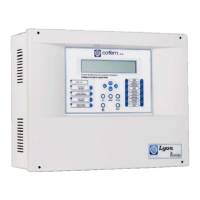
Overview of the control panel's front interface, including keypad and indicators.
Description of the control panel's keypad functions and buttons.
Explanation of the front panel indicator lights (Power, Battery, Test Mode).
Description of the control panel's alphanumeric display screen.
Details the different user access levels and their permissions.
Basic functions and panel activation procedures.
Access for maintenance personnel with specific functions.
Access for competent personnel for system configuration.
Checks to perform before system operation and programming.
Information on power supply requirements and connections.
Procedures for configuring loops and assigning elements.
Troubleshooting guide for system faults and anomalies.
Troubleshooting issues during initial panel startup.
Identifies and resolves issues with power sources.
Covers faults related to sensors, repeaters, and communication.
| Power supply | 230 V AC |
|---|---|
| Protection Class | IP30 |
| Sounder circuits | 2 |
| Battery | 12 V rechargeable battery |
| Material | ABS |
| Operating Temperature | -5°C to +40°C |