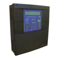
Digital fire detection control panel
COMPACT LYON
16
FIRE PRETECTION MANUFACTURER
Ctra. de Molins de Rei a Rubí, Km. 8,4 - 08191 RUBÍ (Barcelona) ESPAÑA.
Tlf.: +34 935 862 690 - Fax:+34 936 999 261 - cofem@cofem.com - www.cofem.com
1.5.3.4-
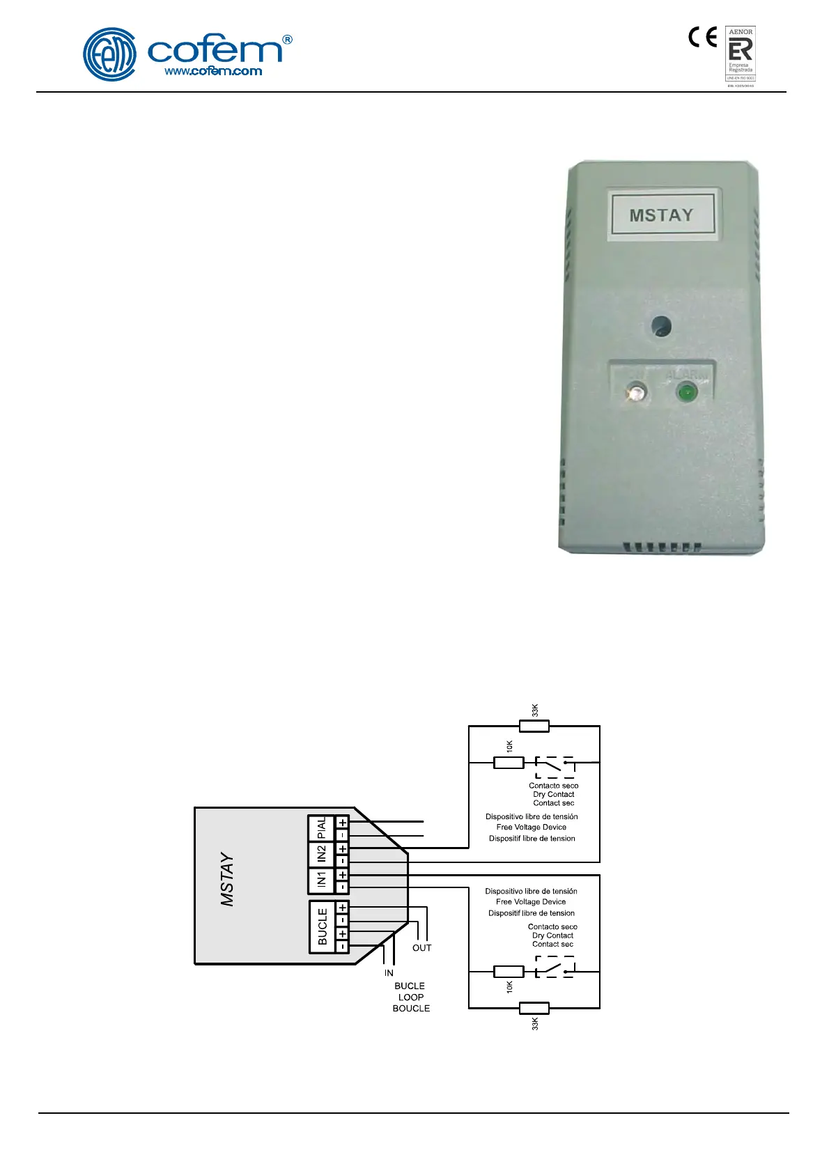
Technical signals module (MSTAY)
Microprocessed analogue and addressable device (with short-circuit
isolator) installed as another element inside the loop.
It has two inputs to distinguish between the open or close state of a
dry contact connected in series with a 10 K resistor. In quiescent
condition, the contact has to be open, and in anomaly condition, the contact
has to be closed. In the first input (marked with IN1), the closed contact is
detected as an ALARM condition. In the second input (marked wit IN2),
the closed contact is detected as FAULT Warning condition. It is possible
to associate both inputs having an alarm and fault conditions information.
In the quiescent condition, the device supervises the electrical
connection through a 33 K resistor, which allows indication of open or
closed electrical connection status.
It is typically used to signal the status of other detection systems that
may exist, as for example, connection of flow sensors in the case of
sprinkler installations, end of travel in the case of fire-resistant doors,
elevators, level of deposits, etc.
The flashing of the transparent red LED indicates communication
with the Control Panel, and if it remains lit, it indicates an alarm status. The
illumination of the green LED indicates activation of one or both inputs.
This device has an output for connection to a remote action indicator, which is activated when in alarm
status. This element is electrical fed through the loop connection.
The MSTAY is conformant with EN 54-18 with the conformity mark awarded by AENOR.
Connection will be made according to figure 6.
Note: To determine the number of MSTAY it can be installed, consult the devices limit per
control panel table (Chapter 1.5).
IN1: Gives an alarm signal to the control panel
IN2: Gives a fault signal to the control panel
Figure 6. Connection schematic MSTAY
 Loading...