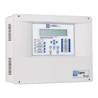
Digital fire detection control panel
COMPACT LYON
54
FIRE PRETECTION MANUFACTURER
Ctra. de Molins de Rei a Rubí, Km. 8,4 - 08191 RUBÍ (Barcelona) ESPAÑA.
Tlf.: +34 935 862 690 - Fax:+34 936 999 261 - cofem@cofem.com - www.cofem.com
Also a name can be assigned to each loop element, called a label. It can be done from the control panel
keys, (see section 3.2.3.3 or Element Configuration Manual), a PC keyboard (see section 3.2.3.3 or Element
Configuration Manual) or by means of a computer, (see Easy Conet Manual).
If the control panel has relay modules (MDA1Y and MDA2Y) and loop sirens (SIRAY / SIRAYL),
one will proceed to the configuration of such depending on the elements that must activate them, from the
control panel keys, (see section, 3.2.3.4.2 or Element Configuration Manual), a PC keyboard (see section,
3.2.3.4.2 or Element Configuration Manual) or by means of a computer, (see Easy Conet Manual).
Optionally the Alarm Zones can be configured from the power station, (see section, 3.2.3.4.3 or
Element Configuration Manual), a PC keyboard (see section, 3.2.3.4.3 or Element Configuration Manual) or
by means of a computer, (see Easy Conet Manual).
Once the previous steps are complete we must verify that the programming performed is correct. For
this we must monitor all the elements in all the loops of the control panel. This will be done from the control
panel keys, (see section 3.2.2.4 or Element Configuration Manual), a PC keyboard (see section 3.2.2.4 or
Element Configuration Manual).
During the startup process, the control panel may display various types of faults. For the Compact
Lyon digital control panel to work correctly, these faults must be resolved. For this, consult section 4.4
which describes the main faults, the causes of them and the action to be taken to resolve them.
4.4- Faults
4.4.1.- FAULTS IN CONTROL PANEL STARTUP
THE CONTROL PANEL DOES NOT TURN ON (POWER SUPPLY AND BATTERY leds off, display
shows nothing)
Cause
Neither the 230V supply nor the batteries are providing the correct voltage to the
panel.
Solution
Check that there is 230 V mains voltage (between 210 V and 250 V) in the terminal strip
for connecting the AC source. Connect fully charged 24 V batteries (between 24 V and
28V).
4.4.2.- POWER SUPPLY FAULTS
MAINS VOLTAGE DROPS (230V voltage does not reach the power source)
Cause
230V voltage does not reach the power source.
Solution
Check that there is 230V mains voltage (between 210V and 250V) in the terminal strip
for connecting the A.C. source. The green led of the A.C. source must be lit. Check the
status of the power supply fuse (8 Amps). (See chapters 2.2.1 and 2.2.3)
MAINS VOLTAGE TOO HIGH
Cause
230V power supply is outside the permitted range.
Solution
Check that there is 230V mains voltage (between 210V and 250V) in the terminal strip
for connecting the A.C. source. The green led of the A.C. source must be lit. (See chapters
2.2.1 and 2.2.3)
NO BATTERY (The battery is not connected to the control panel)
Cause
Either the battery is not connected to the control panel or it is connected incorrectly.
Solution
Check that the batteries are correctly connected to the control panel, and check the status
of the battery output fuse (5 Amps). Carefully examine the battery polarity and check that
they are connected in series. For normal operation, the voltage in the battery output, when
they are connected, should be between 22 V and 28 V. (See chapter 2.3.1)
BATTERIES OVERLOADED (The batteries do not accept a charge)
Cause
The batteries have reached the end of their useful life.
Solution
Replace the set of batteries with new ones. For normal operation, the voltage in the
battery output, when they are connected, should be between 22 V and 28 V. (See chapter
2.3.1)
 Loading...