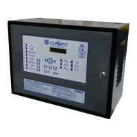
Digital fire detection control panel
COMPACT LYON
FIRE PRETECTION MANUFACTURER 55
Ctra. de Molins de Rei a Rubí, Km. 8,4 - 08191 RUBÍ (Barcelona) ESPAÑA.
Tlf.: +34 935 862 690 - Fax:+34 936 999 261 - cofem@cofem.com - www.cofem.com
BATTERIES DISCHARGED (The batteries are not charged)
Cause
The batteries are not charged, or they are not connected correctly.
Solution
Check that the two 12 V batteries are connected in series, and wait for about 12 hours for
them to finish charging. If the fault persists, replace the batteries with new ones. For
normal operation, the voltage in the battery output, when they are connected, should be
between 22 V and 28 V. (See chapter 2.3.1)
CHARGER FAULT (The battery charger doesn't work)
Cause
The battery charger does not charge the batteries This message is associated with faults
mentioned above, such as: MAINS VOLTAGE DROP, NO BATTERY, BATTERIES
OVERLOADED and BATTERIES DISCHARGED. This message is displayed 4 minutes
after the fault occurs.
Solution
Check the batteries connections and status as indicated above. If this fault is indicated, but
there is no other associated message, checks the battery charger fuse (1 Amp). (See
chapters 2.2.1, 2.2.3 and 2.3.1)
30V FAULT (There is no 30V voltage at the 30V output from the Power Source)
Cause
The fuse for this output has blown due to a short circuit or excessive power consumption.
Solution
Check the connections for the 30V output and check how many elements, such as
repeaters, electromagnets, etc. are connected to it, in order to ensure that the maximum
permissible power consumption is not exceeded. (See chapters 1.5.4.1 and 2.2.3)
RELAY OPEN CIRCUIT:01 (Open circuit for the S1 General Sounder relay)
Cause
There is a lack of continuity between the output of the S1 General Sounder relay and the
end-of-line resistance.
Solution
Check that S1 General Sounder output is correctly connected to the sounders connected to
it, check that the end-of-line resistance (4K7) and check the supervision diodes are
correctly mounted (see chapters 2.3.3.1 and 2.3.3.2). Check the status of the S1 output
fuse (2 Amps). To operate correctly, the S1 General Sounder’s output voltage must be
between -10V and -18V when in standby and between 24V and 29V when activated.
RELAY SHORT-CIRCUITED:01 (Short circuit for the S1 General Sounder relay)
Cause
There is a short circuit between the output of the S1 General Sounder relay and the end-
of-line resistance.
Solution
Check that S1 General Sounder output is correctly connected to the sounders connected to
it, check that the end-of-line resistance (4K7) and check the supervision diodes are
correctly mounted (see chapters 2.3.3.1 and 2.3.3.2). To operate correctly, the S1 General
Sounder’s output voltage must be between -10V and -18V when in standby and between
24V and 29V when activated.
RELAY OPEN CIRCUIT:03 (Open circuit for the S3 General Fault relay)
Cause
There is a lack of continuity between the output of the S3 General Fault relay and the end-
of-line resistance.
Solution
Check that the S3 General Fault output is correctly connected to the devices connected to
it, check that the end-of-line resistance (4K7) and the supervision diodes are correctly
mounted. Check the status of the S3 output fuse (1 Amp). To operate correctly, the S3
General Fault’s output voltage must be between +10V and +18V when in standby and 0V
when activated.
RELAY SHORT CIRCUIT:03 (Short circuit for the S3 General Fault relay)
Cause
There is a short circuit between the output of the S3 General Fault relay and the end-of-
line resistance.
Solution
Check that the S3 General Fault output is correctly connected to the devices connected to
it, check that the end-of-line resistance (4K7) and the supervision diodes are correctly
mounted. To operate correctly, the S1 General Sounder’s output voltage must be between
+10V and +18V when in standby and 0V when activated.
 Loading...