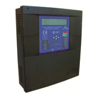
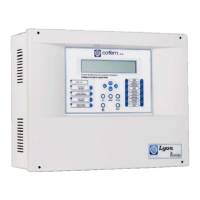
Digital fire detection control panel
COMPACT LYON
26
FIRE PRETECTION MANUFACTURER
Ctra. de Molins de Rei a Rubí, Km. 8,4 - 08191 RUBÍ (Barcelona) ESPAÑA.
Tlf.: +34 935 862 690 - Fax:+34 936 999 261 - cofem@cofem.com - www.cofem.com
2.2- Compact Lyon system connection
Connection of the Lyon digital system will be carried out with 2 x 1.5 mm BRAIDED CABLE
SCREENED HALOGEN FREE, both the loops as well as the sirens, KMAY connected elements and
failure outputs and 30 volt supplies.
The loop must be connected using HALOGEN-FREE SCREENED BRAIDED CABLE 2 x 1.5 mm
for lengths of up to 800 metres and HALOGEN-FREE SCREENED AND BRAIDED CABLE 2 x 2.5
mm for lengths of up to 1500 metres.
Connection of the loop elements will be carried out in accordance with the schematics indicated in
figures 2, 3, 4, 5, 6, 7, 8, 9.
As the assembly of a loop sensor is performed (A30XTA, A30XHA and A30XHTCO), the cover on
each sensor must be replaced until the installation is completely finished and clean.
A list must be made for each loop with the location, type and programming number of each element,
this programming number goes from 1 to the 65533, see the example in the following table:
Loop: 01
POINT Programming no. Label Type Notes
1 12757 ROOM 101 A30XHA
2 12432 ROOM 102 A30XHA
3 4767 BUTTON P1 PUCAY
4 6982 CORRIDOR P1 MDA1Y
DISCONNECT the 230 Voltage circuit and BATTERIES
before accessing the interior of the control panel.
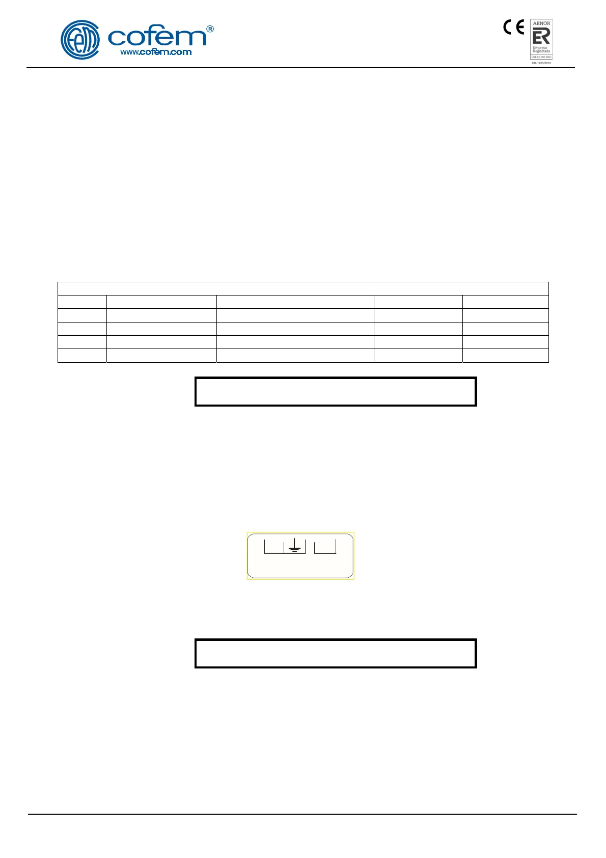
2.2.1- Electrical supply network.
Power supply is 230V ±10% 50 - 60 Hertz. Connection will be made by means of 3 strands with a
minimum section of 1.5mm the connection of the earth cable to the terminal of the switched supply being
obligatory. The maximum consumption for a control panel of up to 2 loops is 70 W.
Connection will be made according to figure 13.
Figure 15. Switched Source
DISCONNECT the 230 Voltage circuit and BATTERIES
before accessing the interior of the control panel.
N L
230 VAC
 Loading...