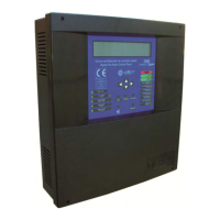
Digital fire detection control panel
COMPACT LYON
FIRE PRETECTION MANUFACTURER 23
Ctra. de Molins de Rei a Rubí, Km. 8,4 - 08191 RUBÍ (Barcelona) ESPAÑA.
Tlf.: +34 935 862 690 - Fax:+34 936 999 261 - cofem@cofem.com - www.cofem.com
1.5.5- Control panel network
1.5.5.1- Installation
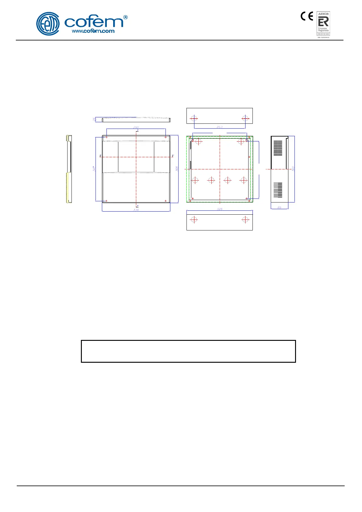
The control panel must be fixed on a vertical wall face. The side slots must be left free for heat to
escape. The dimensions and the pre-drilled holes for cable entry are shown in the following diagram.
Figure 12. Compact Lyon box
Cofem Digital Detection System allows to connect up to 15 control panels in a network, by
connecting 2 wires of 1,5 mm
2
(RS485 communication line). The two wires of the RS485 line will be
connected from the CP NETWORK indication in the CPU card of each control panel.
This connetion is shown in figure 13.
Power is held in each control panel separately. Each control panel will be connected to the
230V mains and its corresponding set of batteries.
The communication cables connection between control panels will be made with cable 2 x 1,5 mm
twisted shielded halogen free, up to a maximum cable length of 1200 meters.
On completing the installation, a 120 Ohm resistor must be connected between the terminals A and B
in the CP NETWORK connector both the first and the last control panel connected.
DISCONNECT the 230V MAINS voltage and the BATTERIES
before handling the inside of the control panel or the repeaters.
1.5.5.2- Operation and configuration
Each control panel in the network displays all information from other control panel and interact with
each other.
Once the power connection, proceed to the configuration in each of the control panels, entering the
number of each (without repeat). For this we perform the following sequence in control panel menu (code
27): Menu (code 27) 4- System configuration (code 9000) 8- Communications 3- Set control panel
number.
After the configuration should perform a general reset at each control panel of the network. For this
we perform the following sequence: Menu (code 27) 8- General reset.
 Loading...