Digital fire detection control panel
COMPACT LYON
28
FIRE PRETECTION MANUFACTURER
Ctra. de Molins de Rei a Rubí, Km. 8,4 - 08191 RUBÍ (Barcelona) ESPAÑA.
Tlf.: +34 935 862 690 - Fax:+34 936 999 261 - cofem@cofem.com - www.cofem.com
12V
12V
-
-
+
-
+
BATERI
-
+
+
+
30
30
-
-
AVERI
S
-
+
S
ALARMA
NC
C
N
S
SIREN
+
-
SIRENA
Sounder
Output of the monitored siren and protected by means of a fuse, to which a delay can be applied by means of
the configuration menu, see 3 chapter configuration.
The installation of sirens will be performed according to the schematic of figure 19. It will be activated
whenever an alarm occurs in the system and the programmed delay has passed. It is only deactivated
when there is no alarm in the system.
ALARMA
Alarm
Unmonitored voltage-free output exit. It is activated whenever an alarm occurs in the system. It is only
deactivated when there is no alarm in the system.
AVERIA
Fault
Monitored fault output and protected by means of fuse, to which a delay can be applied by means of the
configuration menu, see 3 chapter configuration. It will be activated whenever there is a fault in the
system and the programmed delay has passed. It is only deactivated when there is no fault in the system.
30V
output
This is a 30V output that enables the supply of analogue modules or relays or other external devices. This
output is monitored and protected by means of a fuse.
2.3- Components
2.3.1- Batteries
The supervised battery input/output allows the connection of batteries to the control panel. The
batteries are charged through this connection as well as the monitoring of its status. The battery charge is
compensated depending on the temperature of the batteries. This input/output is protected by a fuse and also
against inversion of polarity. In addition to this fuse there is the battery charger fuse.
The capacity of the batteries that are incorporated into the control panel will depend on the number of
loops and additional loads (e.g. relays modules), 7 Ah being the minimum recommended. Batteries with a
capacity of 15 Ah or 24 Ah will have to be housed in a box external to the control panel, ref C-55.
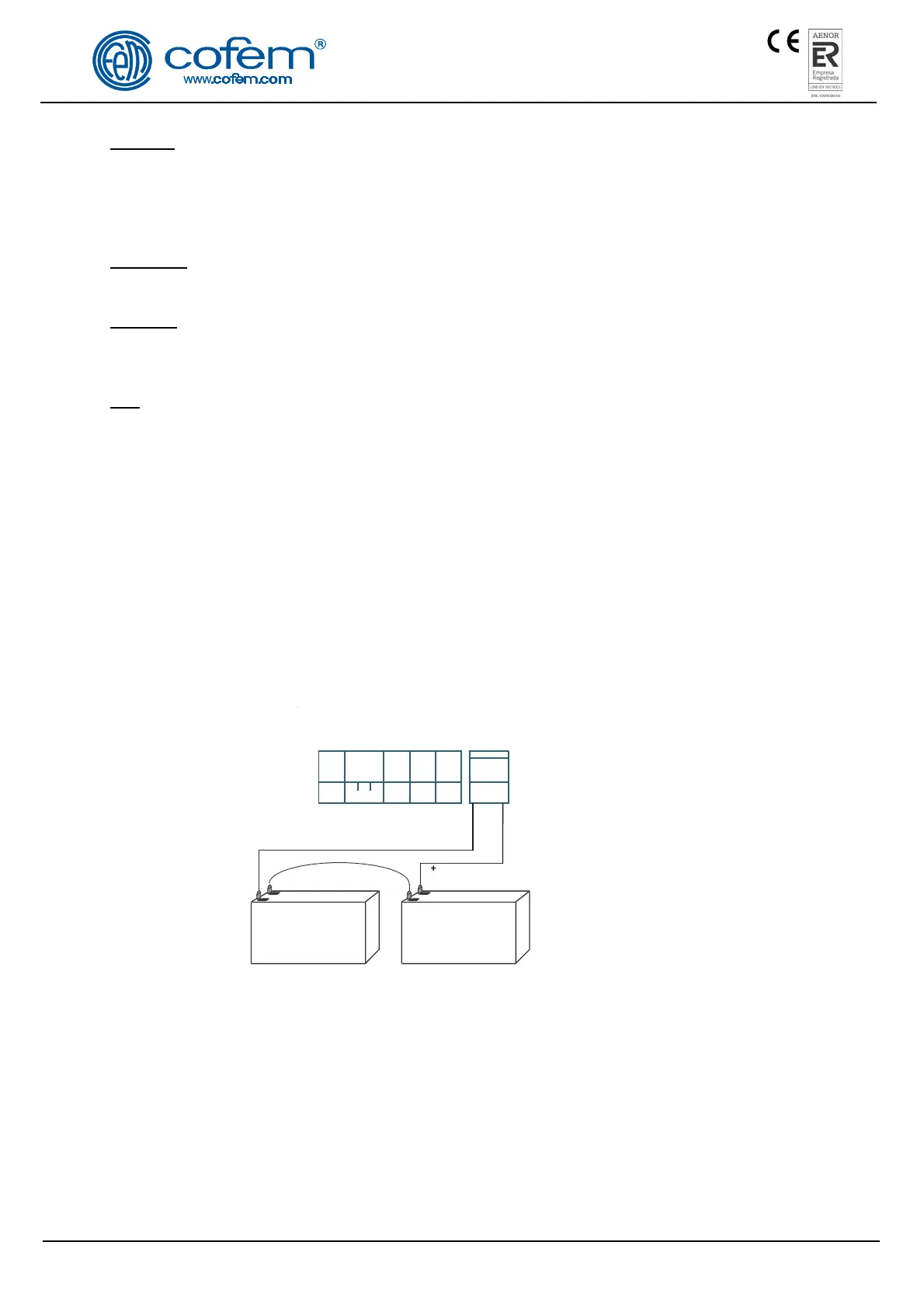
Connection of the two 12V batteries in series is exactly as indicated in figure 18.
Power supply
Figure 18. Battery connection schematic
2.3.2- Connection schematic of a typical loop.
Connection of the Compact Lyon digital system will be made with CABLE OF 2 x 1.5 mm
TWISTED AND SCREENED HALOGEN FREE not only loops but also sounder and fault outputs and
elements connected to the KMAY and the 30V supplies.
The loop is to be connected using 2 x 1.5 mm TWISTED AND SCREENED HALOGEN FREE for
lengths of up to 800 metres and 2 x 2.5 mm TWISTED AND SCREENED HALOGEN FREE for lengths
of up to 1500 metres.
NOTE: For specific details of how each element is to be connected, please see the relevant chapter.
 Loading...