7
P/N EC680-7 April 2017
Order # 5041558-0 & 5041679-0
a. Make sure that the hook latch closes after hanging the hoist.
b. The standard top hook is restrained from rotation by a plate and
two screws. The hook can be made to swivel freely by removing
the plate, or can be rotated 90° and xed in that position.
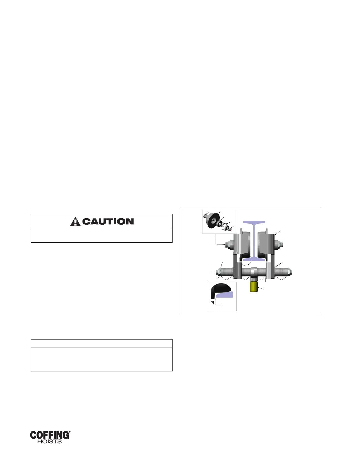
c. See Figure 2-1 for instructions on adjusting lug- mounted plain
trolleys.
d. Refer to Cofng Motorized Trolley Operating and Maintenance
Instructions manual for motorized trolley installation
instructions.
2-3. POWER SUPPLY CONNECTION
a. Disconnect power before making connections.
b. Voltage supplied to the hoist should be within plus or minus
10% of the voltage specied for the hoist. Hoists are tagged at
the factory with a tag indicating the voltage for which the hoist
is wired. Standard single phase hoists are convertible from 115
to 230 volts. Standard single speed, three phase hoists are
convertible from 460 volts to 230 volts. See the Wiring section
(paragraph 7-1) for voltage conversion instructions.
c. National Electrical Code (ANSI C2) and local electrical codes
should be consulted and proper disconnects, branch circuit
protectors, and wiring provided.
d. Power cables furnished with the hoist have a green colored
ground wire which must be securely connected to the electrical
system ground.
e. When installing a three-phase hoist, make only temporary
connections at the power line. Push the "UP" button and observe
the direction of the hook. If it raises, the phasing is correct and
permanent connections may be made at the power line. If the load
block lowers when the "UP" button is pushed, release the button
immediately since the limit switches will not operate to protect
the hoist from over-travel. Reverse the red and black wires at the
power line connection to correct the hook direction.
Do not change connections in the hoist or the pushbutton
assembly.
2-4. VENT PLUG
A pressure relief plug (Item 24, Figure 8-2) is provided which will vent
excess pressure from the transmission housing.
2-5. CHAIN LUBRICATION
The hoist chain should be liberally oiled before placing the hoist into
operation. For lubrication instructions, see paragraph 5-6a.
2-6. TESTING
a. Before placing the hoist into operation, check for proper limit
switch operation. Push the "UP" button and verify that the
hook block stops at least 2 inches from the bottom of the hoist.
Run the hoist down to its lower limit. At least 12 links of chain
should remain on the slack end. If either switch is not correct,
adjust according to the procedure outlined in paragraph 5-2.
NOTE
The upper and lower limit switches are factory set to provide the
maximum allowable hook travel. This travel adjustment should not be
increased. However, the switches may be adjusted to stop the hook
sooner at either end of its travel.
b. Attach a light load to the hook and check the hoist for proper
operation. The load should stop without noticeable drift when
the pushbutton is released. Increase the load to near rated
load. The hoist should still lift the load without hesitation and
stop with no more than one inch drift.
2-7. TROLLEY INSTALLATION
For Motorized, Lug Mounted and Plain Trolley congurations refer to
manual included with the Trolley.
• Motorized Trolley - manual p/n ECMT680-7
• Lug Mounted Trolley - manual p/n CTA698-1
• Plain Trolley - manual p/n CTA698-1
CT-Series Trolleys can be mounted on American Standard I-beams
From 6 to 18 inches high. Adjustment for different beam dimensions
is accomplished with proper placement of spacer washers as
described in below paragraph 2-7.
a. I-Beam Adjustment - Adjustment for I-Beam sizes and
tolerances is accomplished by locating the spacer washers as
shown in Figure 2-1. Normal placement of washers is given in
Table 2-2. Refer to Table 2-1 for identication of part names
and numbers.
BEAM MANUFACTURING TOLERANCES ALLOW WIDE
VARIATIONS FROM HANDBOOK FLANGE WIDTHS, AND
SLIGHT CHANGES TO THE RECOMMENDED WASHER
DISTRIBUTION MAY BE NECESSARY TO SUIT SPECIFIC
INSTALLATIONS.
The particular beam on which your hoist is to be installed
should be measured and trolley spacer washers adjusted to
achieve a clearance of 3/32” to 1/8”.
b. Periodic Inspection - The trolley should be inspected
periodically for evidence of excess wear or overload. Parts
should be replaced as required.
c. Lubrication - Trolley wheels are equipped with sealed, lifetime
lubricated, precision ball bearings which should not require
lubrication for the normal service of the trolley.
See Figure 8-12 and 8-13 for assembly details.
COLUMBUS
McKINNON
C
O
R
P
O
R
A
T
I
O
N
A
1
2
6
6
4
3
7
5555
NOTE: 3.332" FLANGE WIDTH BEAM SHOWN.
3
13
12
11
109
2
WHEEL
BEAM
DETAIL
A
8
Columbus McKinnon Corporation
Amherst, NY USA
NOTICE TO PERSONS RECEIVING THIS DRAWING AND/OR TECHNICAL INFORMATION
A
8
7
6
8
7
6
5
4
3
2
1
B
C
D
B
C
D
CTA PLAIN TROLLEY
1:8
CT-A PLAIN TROLLEY
Modeled:
Drawn:
Approved:
Design Authority:
Original project:
Original scale:
Format
B
Number:
Dimensional Units
INCH
Sheet
Third Angle Projection
Description:
1
1
-
-
-
-
ECN
-
-
Rev.
-
Description of change
Date
-
-
By
-
-
-
-
-
-
Material:
Columbus McKinnon Corporation
Hoist & Rigging - Americas
Amherst, NY USA
Material No:
Standard:
Standard Dimensional
Tolerances Unless
Otherwise Specified
0" to 60" Over 60"
.X
.020 .025
.XX
.010 .015
.XXX
.005 .010
Ang
0
30'
0
30'
Columbus McKinnon Corporation (CMCO) claims proprietary rights in the material disclosed hereon. This drawing and/or technical information is issued in
confidence for engineering information only and may not be reproduced or used to manufacture anything shown or referred to hereon without direct
permission from CMCO to the user. This drawing and/or technical information is loaned for mutual assistance and is subject to recall by CMCO at any time.
This drawing and/or technical information is the property of CMCO.
FIGURE 2-1. CTA TROLLEY



 To Next Page