Connectors and Indicators
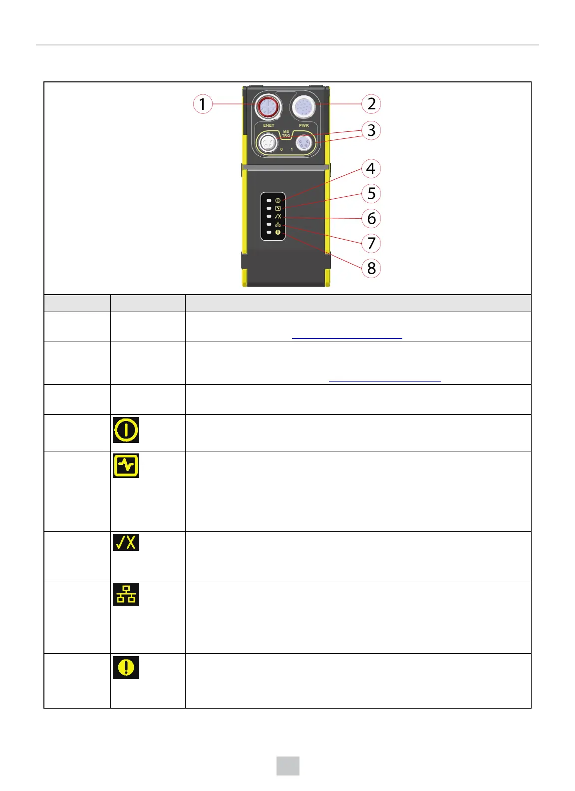
Number Component Description
1 ENETConnector Connects the Ethernet cable, which provides 10/100/1000 Ethernet connectivity. For
more information, refer to Ethernet Cable on page26.
2 PWRConnector Connects the Breakout cable, which provides connections to an external power
supply, the acquisition trigger input, general-purpose inputs and high-speed
outputs. For more information, see Breakout Cable on page27.
3 M/S TRIG
Connectors
Not supported.
4 Power
l Hardware driven, this LED is always ON.
5 Laser Status
l ON: This LED is on when the vision system performs acquisition, and stays
on until the acquisition is complete and a final profile is acquired for a given
image.
l OFF: No acquisition is in progress
6 Pass/Fail
l Green or red when active. You can configure the meaning of this LED in your
In-Sight job.
7 Ethernet status
l OFF: The vision system does not detect Ethernet connection.
l ON: Ethernet connection was established.
l Blinking: Data transmission is in progress.
8 Status
l Green: The vision system is online and running.
l Blank: The vision system is offline.
9
Introduction
 Loading...