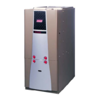
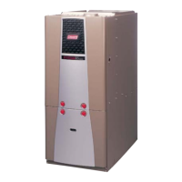
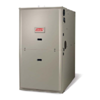
266180-BIM-B-0209
DOWNFLOW/UPFLOW
ELECTRIC FURNACE
MODELS: EB
ISO 9001
Certified Quality
Management System
SECTION I: GENERAL
The following list includes important facts and information regarding the
EB furnace and its packaging inclusions:
1. Furnace is rated at 240 volts, 60 Hz, single phase.
2. Heating and Cooling thermostat is packed with furnace.
3. Filters are furnished with each model, and are the same for all
models - 16 x 20 x 1.
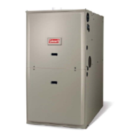
4. Furnace size is the same for all models. See Figure 1.
5. Four-wire thermostat operation for heating and cooling.
6. Coil cavity built into furnace.
7. All furnaces are equipped with an air conditioner blower and is A/C
or Heat Pump ready.
8. Holding strap furnished on top rear of furnace.
9. This furnace is designed for downflow application; however, it may
be converted to an upflow application. (See Page 6 for upflow con-
version instruction.)
10. This furnace must not be operated without the front panel installed.
NOTE: This furnace and its components listed on the A/C and Heat
Pump equipment sticker were listed in combination as a system by
Underwriter's Laboratories for the United States and Canada.
FIGURE 1: Furnace Dimensions
51-5/8”
19-5/8
Sub-Base, if
Used, Adds 7/8”
More to Total
Height and
3/8” to width.
Thermostat
Wiring
Entry
Field
Wiring
Entry
OPTIONAL BOTTOM FIELD
WIRING ENTRY
A
B
C
D
E
F
H
G
J
K
L
M
N
1-7/8”
2-5/8”
3-1/2”
1”
5-1/16”
5-1/2”
1”
5-13/16”
1-3/4”
7-13/16”
8-5/8”
9-7/16”
16-1/2”
J
H
C
B
A
D
E
F
G
N
M
L
K
”
LIST OF SECTIONS
GENERAL . . . . . . . . . . . . . . . . . . . . . . . . . . . . . . . . . . . . . . . . . . . . . . 1
SAFETY . . . . . . . . . . . . . . . . . . . . . . . . . . . . . . . . . . . . . . . . . . . . . . . . 2
UNIT INSTALLATION . . . . . . . . . . . . . . . . . . . . . . . . . . . . . . . . . . . . . 2
DOWNFLOW FURNACE INSTALLATION . . . . . . . . . . . . . . . . . . . . . 3
THERMOSTAT INSTALLATION . . . . . . . . . . . . . . . . . . . . . . . . . . . . .8
OPTIONAL AIR CONDITIONING ACCESSORIES . . . . . . . . . . . . . . .9
WIRING DIAGRAMS . . . . . . . . . . . . . . . . . . . . . . . . . . . . . . . . . . . . .10
LIST OF FIGURES
Furnace Dimensions . . . . . . . . . . . . . . . . . . . . . . . . . . . . . . . . . . . . . . 1
Upflow Closet Clearances . . . . . . . . . . . . . . . . . . . . . . . . . . . . . . . . . . 3
Duct Connector Depth (7990 Series) . . . . . . . . . . . . . . . . . . . . . . . . . . 3
Duct Connector Dimensions (7990 Series) . . . . . . . . . . . . . . . . . . . . . 4
Recommended Floor Cut-out (7990 Series) . . . . . . . . . . . . . . . . . . . . 4
Duct Connector Screw Attachment (7990 Series) . . . . . . . . . . . . . . . . 4
Duct Connector Tab Attachment (7990 Series) . . . . . . . . . . . . . . . . . . 4
Duct System Configuration . . . . . . . . . . . . . . . . . . . . . . . . . . . . . . . . . 5
Installation of Furnace . . . . . . . . . . . . . . . . . . . . . . . . . . . . . . . . . . . . . 5
Hanger Angle Attachment . . . . . . . . . . . . . . . . . . . . . . . . . . . . . . . . . . 5
Blower Bracket and Duct Flange Attachment . . . . . . . . . . . . . . . . . . . .6
Control Box . . . . . . . . . . . . . . . . . . . . . . . . . . . . . . . . . . . . . . . . . . . . . .7
Field Wiring Shield . . . . . . . . . . . . . . . . . . . . . . . . . . . . . . . . . . . . . . . .8
Thermostat Wiring . . . . . . . . . . . . . . . . . . . . . . . . . . . . . . . . . . . . . . . .8
Thermostat Wiring . . . . . . . . . . . . . . . . . . . . . . . . . . . . . . . . . . . . . . . .8
EB10C Wiring Diagram . . . . . . . . . . . . . . . . . . . . . . . . . . . . . . . . . . . .10
EB12C Wiring Diagram . . . . . . . . . . . . . . . . . . . . . . . . . . . . . . . . . . . .10
EB15C Wiring Diagram . . . . . . . . . . . . . . . . . . . . . . . . . . . . . . . . . . . .11
EB17C Wiring Diagram . . . . . . . . . . . . . . . . . . . . . . . . . . . . . . . . . . . .11
EB20C Wiring Diagram . . . . . . . . . . . . . . . . . . . . . . . . . . . . . . . . . . . .12
EB23C Wiring Diagram . . . . . . . . . . . . . . . . . . . . . . . . . . . . . . . . . . . .12
LIST OF TABLES
Duct Connector for Electric Furnaces . . . . . . . . . . . . . . . . . . . . . . . . . 3
Wiring Requirements . . . . . . . . . . . . . . . . . . . . . . . . . . . . . . . . . . . . . . 6
EB Series Blower Performance . . . . . . . . . . . . . . . . . . . . . . . . . . . . . .7
Electrical Data . . . . . . . . . . . . . . . . . . . . . . . . . . . . . . . . . . . . . . . . . . . .7