EasyManua.ls Logo

Coleman Powermate VP0000301 - User Manual

Coleman Powermate VP0000301
20 pages
Print Icon
To Next Page IconTo Next Page
Loading...
200-2484
Revision A
Operator-Parts Manual
Manuel de l’opérateur - Manuel de pièces
Manual del operador - Manual de piezas
Oilless, Single Stage, Direct Drive, Electric Air Compressors
Sans l’huile, d’une seul étape, à prise directe, compresseurs d’air
électriques
Sin aciete, de una sola etapa, de mando directo, compresores de aire
eléctricos
6-05
WARNING: Read and understand all safety precautions in this manual before operating. Failure to comply with
instructions in this manual could result in personal injury, property damage, and/or voiding of your warranty. The
manufacturer WILL NOT be liable for any damage because of failure to follow these instructions.
AVERTISSEMENT : Lisez et veillez à bien comprendre toutes les consignes de sécurité de ce manuel avant
d'utiliser l'appareil. Toute dérogation aux instructions contenues dans ce manuel peut entraîner l'annulation de la
garantie, causer des blessures et/ou des dégâts matériels. Le fabricant NE SAURA être tenu responsable de dommages
résultant de l'inobservation de ces instructions.
ADVERTENCIA: Lea y comprenda todas las precauciones de seguridad contenidas en este manual antes de
utilizar esta unidad. Si no cumple con las instrucciones de este manual podría ocasionar lesiones personales, daños a la
propiedad y/o la anulación de su garantía. El fabricante NO SERÁ responsable de ningún daño por no acatar estas
instrucciones.
Specification Chart________Tableau des spécifications_______Cuadro de especificaciones
Questions? See back page._____Questions ? Consultez la page final._____¿Preguntas? Vea la página final.
?
MODEL NO.
(MODÈLE)
(MODELO)
TANK CAPACITY
GALLONS
(CAPACITÉ DU
RÉSERVOIR - LITRES)
(CAPACIDAD DEL
TANQUE - LITROS)
VOLTAGE/AMPS/
PHASE
(TENSION/AMPS/
PHASE)
(VOLTAJE/AMP/FASE)
KICK-IN
PRESSURE
(PRESSION
D’OUVERTURE)
(PRESION DE
CONEXION)
KICK-OUT
PRESSURE
(PRESSION DE FERM.)
(PRESION DE
DESCONEXION)
VP0000301 3 (11,4) 120/6.5/1 70 (4,83 bar) 100 (6,89 bar)
VP0000301.01 3 (11,4) 120/6.5/1 70 (4,83 bar) 100 (6,89 bar)
VP0000401 4 (15,1) 120/6.5/1 70 (4,83 bar) 100 (6,89 bar)
Question and Answer IconNeed help?

Do you have a question about the Coleman Powermate VP0000301 and is the answer not in the manual?

Overview

This document describes oilless, single-stage, direct-drive, electric air compressors, providing essential information for their operation, maintenance, and troubleshooting.

Function Description

These are electric air compressors designed to compress air without the need for oil lubrication. They are single-stage, meaning they compress air in one step, and direct-drive, indicating that the motor directly powers the pump. The compressed air is stored in a tank and can be used to power various air tools and accessories. The compressor operates automatically, starting when the tank pressure drops to a preset kick-in pressure and stopping when it reaches a preset kick-out pressure.

Important Technical Specifications

The manual provides a specification chart detailing three models: VP0000301, VP0000301.01, and VP0000401.

  • Tank Capacity:
    • VP0000301 and VP0000301.01: 3 gallons (11.4 litres)
    • VP0000401: 4 gallons (15.1 litres)
  • Voltage/Amps/Phase: All models operate on 120V, 6.5 Amps, single-phase power.
  • Kick-in Pressure: All models have a kick-in pressure of 70 PSI (4.83 bar).
  • Kick-out Pressure: All models have a kick-out pressure of 100 PSI (6.89 bar).

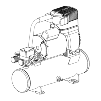
The basic components include an electric motor, pump, pressure switch, and tank. The electric motor (A) powers the pump and is equipped with an automatic reset overload protector that shuts down the motor if it overheats, restarting automatically once cooled. The pump (A) compresses air into the tank (B). The pressure switch (A) controls the motor, stopping it at the kick-out pressure and restarting it at the kick-in pressure. A tank pressure gauge (C) displays the stored air pressure, and an air pressure regulator (D) allows adjustment of the outlet pressure to match the tool's requirements, with the regulated pressure gauge (E) showing the adjusted output. The air line outlet (F) is a 1/4" NPT fitting for connecting air hoses.

Usage Features

Assembly:

  1. Unpack and inspect the compressor for damage.
  2. Verify the model and pressure rating from the serial label.
  3. Position the compressor near a grounded electrical outlet, at least 12 inches (31 cm) from any wall or obstruction, in a clean, well-ventilated area. Avoid extension cords; use a longer air hose instead. In cold climates, store portable compressors in a heated building when not in use to prevent motor starting issues and water condensation freezing.
  4. Connect a 1/4" NPT air hose to the compressor hose outlet (A).

Daily Startup:

  1. Set the ON/OFF switch (A) to OFF.
  2. Close the tank petcock (D) by turning it clockwise.
  3. Plug in the power cord.
  4. Turn the ON/OFF switch (C) to ON.
  5. If present, adjust the pressure regulator to the tool's working pressure. When adjusting from higher to lower pressure, turn the knob counterclockwise past the desired setting, then clockwise to reach the desired pressure. Never exceed the maximum working pressure of the tool.

Shutdown:

  1. Set the ON/OFF switch (A) to OFF.
  2. Unplug the power cord.
  3. Reduce pressure in the tank through the outlet hose. The relief valve ring (E) can also be pulled to release pressure.
  4. Tip the compressor (if necessary) so the petcock is at the bottom of the tank, then open the petcock (B) to drain moisture. Wear safety goggles when opening the petcock to prevent eye injury from propelled debris.

Electrical Power Requirements:

  • Refer to the serial label for voltage and amperage.
  • Extension Cords: Avoid using extension cords. If unavoidable, use a 3-wire, 3-blade grounding cord no longer than 50 feet (15 m) and with a minimum wire size of 12 gauge (AWG). Smaller gauge cords can cause voltage drop and overheating.
  • Grounding: The product must be grounded to reduce electric shock risk. It has a 3-prong grounding plug that must be connected to a properly installed and grounded 3-slot outlet. Do not modify the plug or use adapters. Consult a licensed electrician if grounding instructions are unclear.

Maintenance Features

General Maintenance: Regular maintenance ensures trouble-free operation. The following items should be inspected regularly:

  • Checking the Relief Valve: Pull the relief valve ring daily to ensure it functions properly and is free of obstructions.
  • Testing for Leaks: Check all connections for tightness. Spray soapy water around suspected leak areas; if bubbles appear, repair or replace the faulty component. Do not overtighten connections.
  • Draining the Tank: Condensation accumulates in the tank and must be drained at the end of every workday to prevent corrosion. Relieve air pressure, open the petcock (B), and tilt the tank to drain. Wear protective eyewear. In cold climates, drain the tank after each use to prevent freezing.
  • Storage: Before prolonged storage, clean dust and debris from the compressor with an air blow gun. Disconnect and coil the power cord. Release all tank pressure using the relief valve. Drain all moisture from the tank. Cover the unit to protect it from moisture and dust.

Troubleshooting Chart: The manual includes a comprehensive troubleshooting chart to diagnose and resolve common issues:

  • Low pressure or not enough air / Compressor does not stop:
    • Possible causes: Open tank petcock, fittings leak, restricted air intake, prolonged excessive use of air, compressor not large enough.
    • Solutions: Close petcock, check/reseal fittings (do not overtighten), clean/replace air filter, decrease air usage, check accessory air requirement (may need a larger compressor).
  • Air leaks from regulator, or regulator does not regulate pressure:
    • Possible causes: Hole in air hose, tank leaks, blown seals, valve leaks, leaking/worn piston, dirty/damaged regulator internal parts.
    • Solutions: Check/replace air hose, immediately replace tank (do not repair), replace compressor assembly, replace regulator/internal parts.
  • Regulated pressure gauge reading drops when air accessory is being used:
    • Possible causes: Normal operation, compressor not large enough.
    • Solutions: Adjust regulator while accessory is used, check accessory air requirement (may need a larger compressor).
  • Pressure relief valve opens:
    • Possible causes: Tank pressure exceeded normal operating pressure, pressure switch stuck.
    • Solutions: Replace pressure switch.
  • Motor will not run:
    • Possible causes: Tank pressure exceeds preset pressure switch limit, motor overload protection tripped, fuse blown/circuit breaker tripped, check valve stuck open, pressure bleeder valve on pressure switch not unloaded, wrong wire gauge/excessive extension cord length, loose electrical connections, defective capacitor, paint spray on internal motor parts, defective motor.
    • Solutions: Motor will start automatically when tank pressure drops, let motor cool off (overload switch resets automatically), replace fuse/reset circuit breaker (do not use higher rating), check proper fuse ("Fusetron" type T), check low voltage/extension cord size, disconnect other applications (operate on dedicated circuit), remove/clean/replace check valve, bleed line by moving pressure switch lever to OFF before restarting (replace bleeder valve if it doesn't open), check wire gauge/extension cord length, contact authorized service center (for capacitor, motor parts, or motor).

Coleman Powermate VP0000301 Specifications

General IconGeneral
BrandColeman
ModelPowermate VP0000301
CategoryAir Compressor
LanguageEnglish

Related product manuals