7
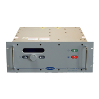
6.4 Fault Indicators: Yellow LED’s indicate fault conditions of over-temp, over-voltage, over-
current, and over-power.
6.5 Local RF enable toggle switch.
6.6 Local power control pot.
6.7 Monitor meter with select switch: Digital panel meter measures 4-way switch selectable-
delivered RF power, reflected power, output frequency, Local or Remote setpoint.
7. Remote Analog Interface
Pins 25(+) & 12(-), FWD OUT: Linear 0-10 differential analog out representing 0-5KW RF
output forward power. 1K output impedance.
Pins 24(+) & 11(-), RFL OUT: Linear 0-10 differential analog out representing 0-5KW RF output
reflected power. 1K output impedance.
Pins 23(+) & 10(-), DEL PWR OUT: Linear 0-10 VDC differential analog out representing 0-
5KW RF output delivered power. 1K output impedance.
Pins 22(+) & 9(-), SETPOINT IN: 0 - 10 VDC volt differential analog input giving linear
response to 0-5KW delivered output power. 10 K input impedance.
Pins 21(collector) & 8(emitter), MAX POWER LIMIT: Opto isolated digital output representing
an output delivered power condition over 5.1KW.
Pins 20(collector) & 7(emitter), OVERTEMP: Opto isolated digital output representing a latched
over-temp condition. RF must be disabled via RF ENABLE IN to reset overtemp latch.
Pins 19(collector) & 6(emitter), RF ENABLED OUT: Opto isolated digital output representing
RF has been enabled via RF ENABLE IN.
Pins 18(cathode) & 5(anode), RF ENABLE IN: Opto isolated digital input that enables RF output.
Activate input to enable. 2K input impedance.
Pins 17(anode) & 4(cathode), REMOTE SELECT: Opto isolated digital input to enable remote
operation. Activate for remote. 2K input impedance.
Pins 16(anode) & 3(cathode), FWD/DEL SELECT: Opto isolated digital input to select power
control loop from delivered to forward. Activate for forward control. 2K input impedance.
Pins 15(+) & 2(RET), Aux 15VDC output, 50 mA available MAX.
Pins 14 & 1, INTERLOCK LOOP: For External control of generator AC contactor. Pull-in
current at 24VAC is 350mA continuous (2A peak).
B. Mechanical Specifications
1. Size: nominal, standard 19” rack mount 16.75”W x 10.5”H x 24.125”D
(425 mm W x 267 mm H x 613 mm D)
2. Weight: 200lbs (91 kg)