EasyManua.ls Logo

Comelit 1205/B User Manual

Comelit 1205/B
128 pages
Go to English
To Next Page IconTo Next Page
Page #1 background imageLoading...
Page #1 background image
Assistenza tecnica Italia 0346/750090
Commerciale Italia 0346/750091
Technical service abroad (+39)0346750092
Export department (+39) 0346750093
www.comelitgroup.com
PT
MANUAL
TÉCNICO
IT
MANUALE
TECNICO
EN
TECHNICAL
MANUAL
FR
MANUEL
TECHNIQUE
NL
TECHNISCHE
HANDLEIDING
DE
TECHNISCHES
HANDBUCH
ES
MANUAL
TÉCNICO
1
2
Manuale tecnico Smart kit monofamiliare Art. 8471S
Technical manual for single-family Smart Kit Art. 8471S
Manuel technique Smart kit un usager Art. 8471S
Technische handleiding Smart kit eengezinswoning Art. 8471S
Technisches Handbuch Smart Kit Türsprechanlage
für Einfamilienhaus Art. 8471S
Manual técnico Smart Kit unifamiliar art. 8471S
Manual técnico Smart Kit monofamiliar art. 8471S

Table of Contents

Question and Answer IconNeed help?

Do you have a question about the Comelit 1205/B and is the answer not in the manual?

Comelit 1205/B Specifications

General IconGeneral
BrandComelit
Model1205/B
CategoryIntercom System
LanguageEnglish

Summary

Technical Manual for Single-Family Smart Kit Art. 8471S

Programming Ranges and Ringtones

Minimum Range Address

Sets minimum address for range programming. Refer to TAB. A page 26.

Maximum Range Address

Sets maximum address for range programming. Refer to TAB. A page 26.

Enable Range

Enables the specified range for operation.

Disable Range

Disables the specified range for operation.

Programming Input IN1 for Signal Indication

Input IN1 → LED (default)

Configures IN1 for LED indication, default setting.

Input IN1 → ALARM

Configures IN1 for alarm signal indication.

Input IN1 ⇒ LOCK-RELEASE

Configures IN1 for lock-release signal indication.

Input IN1 ATTUATOR CODED

Configures IN1 for coded actuator indication.

Input IN1 GENERIC ACTUATOR

Configures IN1 for generic actuator indication.

Special Programming for Art. 4882

Lock Functions

Programming options related to door lock functions.

System Functions

Programming options for general system functions.

Internal Units Art. 6302

Installing Door-Entry Phone Art. 2608

General Installation and Operation Instructions

Operating Distances Table

Table showing maximum cable lengths and distances for different components.

Button Functions and Settings

Monitor and Door-Entry Phone Settings

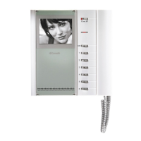
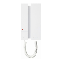
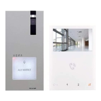
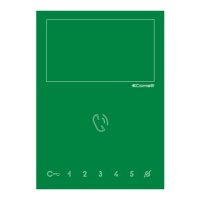
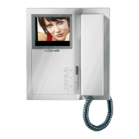
Configuration for monitors and door-entry phones.

Default Button Settings

Programming Buttons for Actuators

Guide to programming buttons for generic or coded actuators.

Intercom Call Programming

Programming/Deleting Intercom Addresses

Procedure for managing selective intercom addresses.

Programming Buttons for Intercom Calls

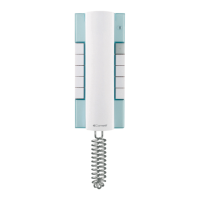
Assigning functions to buttons for intercom calls.

Programming Buttons for Other Functions

Direct Intercom Call Programming

Intercom Call Programming Procedure

Steps for programming intercom calls, including mode entry, volume adjust, and unit programming.
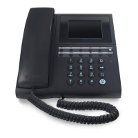
Programming Reset

IN1 Input for Signal Indication (Closure)

IN1 Input for Signal Indication (Voltage)

RC Network for Door Lock Filter

Related product manuals