Do you have a question about the Comelit Simplebus 2 FT SB2 15 and is the answer not in the manual?
General precautions for installation, usage, and maintenance of electrical devices.
Information on product compliance with directives and safety standards.
Details on connecting the mixer-power supply unit to the system and power.
Step-by-step guide for installing Bravo and Genius monitors.
Guidelines for cleaning the equipment using a damp cloth.
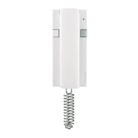
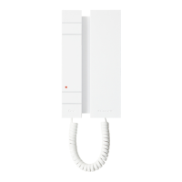
Description of the 3-position selector for ringtone volume and privacy function.
Explanation of the LED indicator for system status and functions.
Function of the door-open button.
Details on the function and programming of Button 1.
Details on the factory setting for the self-ignition function of Button 2.
Information on optional buttons 3 and 4 and their activation with Art. 5733.
Information on optional buttons 5 and 6 and their use with Art. 5733/5734.
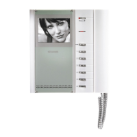
Description of the monitor screen for image display and interchangeable masking.
Explanation of the controls for adjusting monitor brightness and contrast.
Description of the memo label for indicating monitor button functions.
Function of the monitor handset for initiating communication.
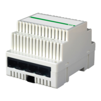
Description of connectors, terminal blocks, and specific input/output terminals on the bracket.
Details on the function of various jumpers and microswitches for configuration.
Information on customising button functions and details on Simplebus 2 systems.
Explanation of the door-open button and the 3-position ringtone/privacy selector.
Details on the system connection terminals for bus line, call input, and call repetition.
Function of JP2 jumper for selecting P1 button operation (call or actuator).
Function of CV1/CV2 jumpers for obtaining a C. NO. contact.
Description of dip switches for user code and the microphone volume adjustment trimmer.
How devices are identified by codes and set using DIP switches on the unit or bracket.
Procedure for setting the user code based on the programming table.
Warnings and operational modes for Art. 4660 modules as external units.
Step-by-step guide for programming buttons using Art. 4660 modules and DIP switches.
Function of the 8-selector dip switches for setting code ranges on the switching device.
Guidelines for setting user codes and ensuring non-overlapping ranges for multiple devices.
Example of how to set a DIP switch combination for a specific code.
Information regarding the reservation of code 240 for the porter switchboard function.
Rules for routing cables, using specific terminals, and assessing connection distances.
Information on specific components for system configuration variants like cascade connections.
Recommendations for positioning external unit cameras to ensure optimal image quality.
Guidelines for using different cable types and avoiding parallel wire connections.
Diagrams showing distances and connection layouts for different cable types.
Table detailing how to set the Art. 1216 based on the type of connection cable used.
Process of a visitor calling and establishing communication with the internal unit.
Function of the electric lock button and caller illumination LEDs on the external unit.
Operation of monitor self-ignition, toggle function between entrances, and privacy settings.
Usage details for handset, brightness, volume, and hanging up the receiver.
Differences in behaviour between main and secondary monitors upon receiving calls or self-ignition.
How to enable, disable, and operate the monitor self-ignition function.
How to use the video request function with secondary monitors for viewing external unit images.
Step-by-step guide to select and confirm different ringtones for monitor calls.
Table correlating cable types with maximum connection distances shown in the diagram.
Instruction to cut the resistance of the used output for specific system configurations.
Rules and limits for connecting multiple internal units in a cascade configuration.
Procedure for cascading multiple Art. 4834/9 concentrators with an amplifier.
Rules and wiring guidelines for connecting call repetition devices and managing inductive loads.
How to use button P1 for different purposes, including jumper configurations.
| Video | Yes |
|---|---|
| Camera | Yes |
| Mounting | Wall-mounted |
| Compatibility | Comelit Simplebus 2 system |
| Power Supply | Bus-powered |
| Communication | 2-wire |
| Audio | Yes |
| Housing Material | Plastic |
| Model | FT SB2 15 |