Do you have a question about the Comelit MT SB2 01 and is the answer not in the manual?
Overview of the Simplebus2 system, its 2-wire technology and capabilities.
Guidelines to reduce the risk of faults and electric shocks during installation and use.
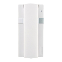
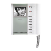
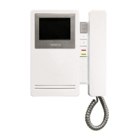
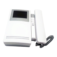
Description, technical characteristics, and components of the Art. 4700W monitor.
Important warnings for correct installation and safe usage of the system components.
Details and features of Art. 4700W/I semi flush-mounted and Art. 4701W/A surface-mounted monitors.
Information on flush-mounting boxes Art. 4514 and Art. 4517 for monitor installation.
Description, technical characteristics, and connection terminals of the Art. 4714W/2 bracket.
Instructions for installing monitors using surface-mounting and desk conversion kits.
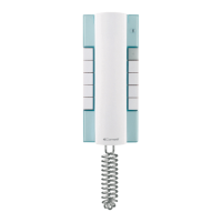
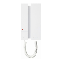
Description, technical characteristics, and functions of the Art. 2408W/A telephone handset.
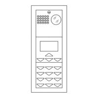
Details on Powercom Series speaker units, including audio and video models.
Various types of flush-mounting boxes, housings, and specialized modules for external units.
Instructions for mounting boxes and connecting cables to external units.
Steps for assembling modules, dismantling faces, and adjusting components like the microphone.
Instructions for connecting cables, inserting modules, and managing labels for information modules.
Details on transformers, relays, and switching devices used in the system.
Information on power supplies for additional monitors and line distribution terminals.
Technical specifications for the Art. 1195 transformer.
Description and configuration of the Art. 4896 mixer-power supply unit.
Information on the specific Simplebus2 cable and related accessories like relays.
Details on line amplifiers and concentrators for signal distribution.
Rules for avoiding interference, wiring, and terminating risers.
Guidelines for connecting multiple units, cascade connections, and distance limitations.
Tables detailing maximum distances based on cable type and system components.
Diagrams illustrating system connections and maximum permitted distances.
How to set user codes for telephones and brackets using dip switches.
Programming the Art. 1224 switching device using dip switches for code ranges.
A comprehensive table mapping user codes to specific dip switch configurations.
Steps for programming external units and setting them as main or secondary.
Table showing Art. 1216 settings based on the type of connection cable used.
How calls are received, communication is established, and basic functions operate.
Details on self-ignition, privacy function, and monitor settings.
Wiring diagram for a 1-door Logicom Series audio system (SBC/01L).
Wiring diagram for a 1-door Powercom Series audio system (SBC/01).
Wiring diagram for a 1-door digital audio Logicom system (SBC/02L).
Wiring diagram for a 2-door digital audio Powercom system (SBC/02).
Wiring diagram for a 1-door video entrance Logicom system (SB2V/01L).
Wiring diagram for a 1-door video entrance Powercom system (SB2V/01).
Wiring diagram for a 2-door video entrance Logicom system (SB2V/03L).
Wiring diagram for a 2-door video entrance Powercom system (SB2V/03).
Wiring diagram for a Powercom system with one entrance and up to four mixer-power supplies.
Wiring diagram for video systems with two entrances and a porter switchboard.
Wiring diagram for Logicom systems with one main and up to four secondary video entrances.
Wiring diagram for Powercom systems with one main and up to four secondary video entrances.
Variants for connecting multiple users sharing the same code, up to three units.
Diagram for connecting monitors with the same user code in a branched configuration.
Diagram for connecting monitors with the same user code in a cascade configuration.
Diagram for cascade connecting monitors with the same code and separate power supplies.
Diagrams for cascade and branched telephone connections in mixed systems.
Diagram showing connection of up to 4 riser branches to a Mixer-Power Supply.
Diagram showing cascading of Art. 4834/2 units with a video amplifier.
Diagram for connecting call repetition devices to telephones and monitors.
Variants for using push-button 2 and local floor call on telephones.
Variants for using push-button 2 and local floor call on the Art. 2428W telephone.
Variant for using push-button 1 of the monitor on the bracket.
Variant for setting the bracket as secondary to enable video request.
Variant for using local floor call functionality with brackets.
Variant for enabling optional self-ignition on monitors with main brackets.
Instructions for activating the Privacy function using the optional Art. 4703 card.
| Brand | Comelit |
|---|---|
| Model | MT SB2 01 |
| Category | Intercom System |
| Language | English |