Do you have a question about the Comelit Bravo Color and is the answer not in the manual?
| Brand | Comelit |
|---|---|
| Model | Bravo Color |
| Category | Intercom System |
| Language | English |
Provides detailed technical information for the two-family system.
French technical manual for the Bravo Kit Color system.
Dutch technical manual for the Bravo Kit Color system.
German technical manual for the Bravo Kit Color system.
Spanish technical manual for the Bravo Kit Color system.
Crucial instructions for safe installation and operation of the equipment.
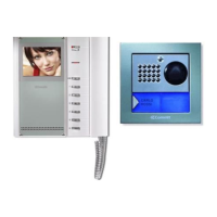
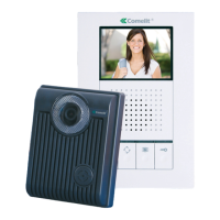
Introduces external and internal units and general system info.
Describes the system's purpose and external unit's technical specs.
Details the connections on the external unit's terminal block.
Step-by-step instructions for installing the external unit.
Instructions on adjusting the microphone position for optimal performance.
Steps for inserting nameplates for user identification.
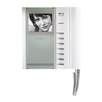
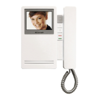
Describes the features and controls of the Art. 5702 monitor.
Outlines the technical specifications for the Art. 5714KC unit.
Explains the purpose and usage of various buttons on the units.
Guide for installing the Art. 5702 as a flush or wall-mounted device.
Instructions for installing optional expansion cards.
Details the privacy function, ringtone settings, and programming options.
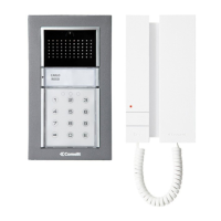
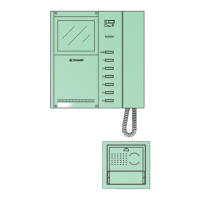
Step-by-step process for installing the Art. 2608 door-entry phone.
Provides rules and limits for system installation and basic operation.
Shows maximum cable lengths for different cable types and configurations.
Explains system behavior during calls and intercom communication.
Configuration of dip switches for call address and operating mode.
Maps dip switch settings to specific call addresses.
Maps dip switch settings to system operating modes.
Defines the role of the bracket within the system setup.
Details specific button actions like actuator, self-ignition, and switchboard calls.
Guide on how to select different ringtones for various call types.
How to integrate Bravo Kits with a main entrance panel using Art. 4680KC.
Specific procedure for programming the Art. 4680KC unit buttons.
Detailed dip switch settings for various functions like heating, messages, and door lock.
Programming for actuator control and system-wide functions.
Illustrates the basic wiring for a two-family kit with cascade connection.
Shows specific terminal connections for system components.
Points to pages with detailed information on operating distances.
Illustrates the basic wiring for a two-family kit with branch connection.
Shows specific terminal connections for system components.
Points to pages with detailed information on operating distances.
Shows wiring for a two-family kit extended with a second unit via branch connection.
Details specific terminal connections for the extended system.
Shows wiring for a two-family kit extended with a second unit via cascade connection.
Details specific terminal connections for the extended system.
Illustrates wiring for a two-family kit with an added power supply unit.
Details specific terminal connections for the system with extra power.
Diagram for connecting the remote camera module Art. 1259C.
Refers to a separate manual for setting up and operating the camera module.
Diagram for connecting multiple Bravo Kits to a main entrance panel using Art. 4834/9.
Details limitations on which modules Art. 4680KC can manage.
Diagram for connecting up to 30 Bravo Kits in cascade using Art. 1424.
Points to further information for Art. 4833C, 4834/9, and 1224A.
Diagram showing the connection of the video amplifier Art. 4833C.
Illustrates adding a main monitor in parallel using cascade connection.
Shows adding a main monitor in parallel with branch connection.
Connects one main and one secondary monitor with the same user code.
Connects one main and one secondary monitor in cascade with the same user code.
Shows connecting additional door-entry phones via branch from the monitor.
Connects additional door-entry phones in cascade from the monitor.
Adds a door-entry phone in parallel via branch connection from the riser.
Instructions for connecting call repetition devices Art. 1229 or 1122/A.
Covers connection limits and capacitor use for inductive loads.
Explains various uses for button P1 on Art. 5714KC.
Describes the function of the LED 1 terminal and its indicator light.
Explains various uses for button P1 on Art. 2608.
Shows a variant for connecting floor door calls.
Diagram for connecting the actuator relay Art. 1256.
Using the external unit relay for lock-release or actuator control.
Variant for security door lock with additional power supply.
Using an RC network to filter door lock relay contacts.
Wiring for door open indication using a specific variant.