3
• Install the equipment by carefully following the
instructions given by the manufacturer and in compliance
with the standards in force.
• All the equipment must only be used for the purpose it
was designed for. Comelit Group S.p.A. declines any
responsibility for improper use of the apparatus, for any
alterations made by others for any reason or for the use
of non-original accessories or materials.
• Installation, mounting and assistance procedures for
electrical devices must only be performed by specialised
electricians.
• For standard-compliant installation, a suitable (two-pole)
device must be provided for isolating and protecting the
mains power supply in the building's electrical system,
in compliance with current standards (law 46/90). There
must be a gap of at least 3 [mm] between the isolating
device contacts.
WARNING
• Disconnect the power supply before carrying out any
maintenance procedures.
• It is recommended to check the correct operation of the
safety system periodically (at least once a month).
• Remove any dust accumulated in the control panel
housing with a damp cloth, without using any solvent,
and check that there are no foreign bodies.
• Check the condition of the connectors and the
conductors.
• Carry out the maintenance and operation test of all the
components (smoke sensors, movement sensors, ...) as
indicated in the respective technical manuals.
• Replace the protections on the terminals.
Service
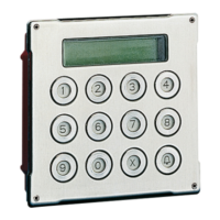
MAIN FEATURES:
• Initial addressing from built-in keypad.
• Two universal inputs, configurable as NC, NO, single, double and triple balance, triple balance with jamming, double zone and
double zone with termination, with the option of direct connection of roller shutter contacts.
• On-board 485 bus end-of-line resistor, which can be activated by DIP switch.
• Anti-tamper and anti-tear tamper.
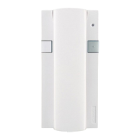
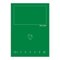
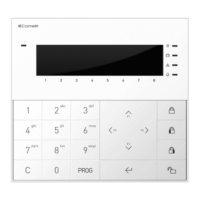
1. Indicator LED
2. Display
3. Function keys (programmable)
4. RFID reader (only for Art.
VEDOKPR / VEDOKPR200)
5. Light sensor*
6. terminal block
TECHNICAL SPECIFICATIONS
Features Value
Consumption (min./max.)
30 mA with LEDs o ,
80 mA during alarm alert
Operating voltage 10 V
to 15 V
Operating temperature and
Operating humidity
-10° / + 55° with warm dry air
-10° / + 40°C with max + 93% RH (not condensed)
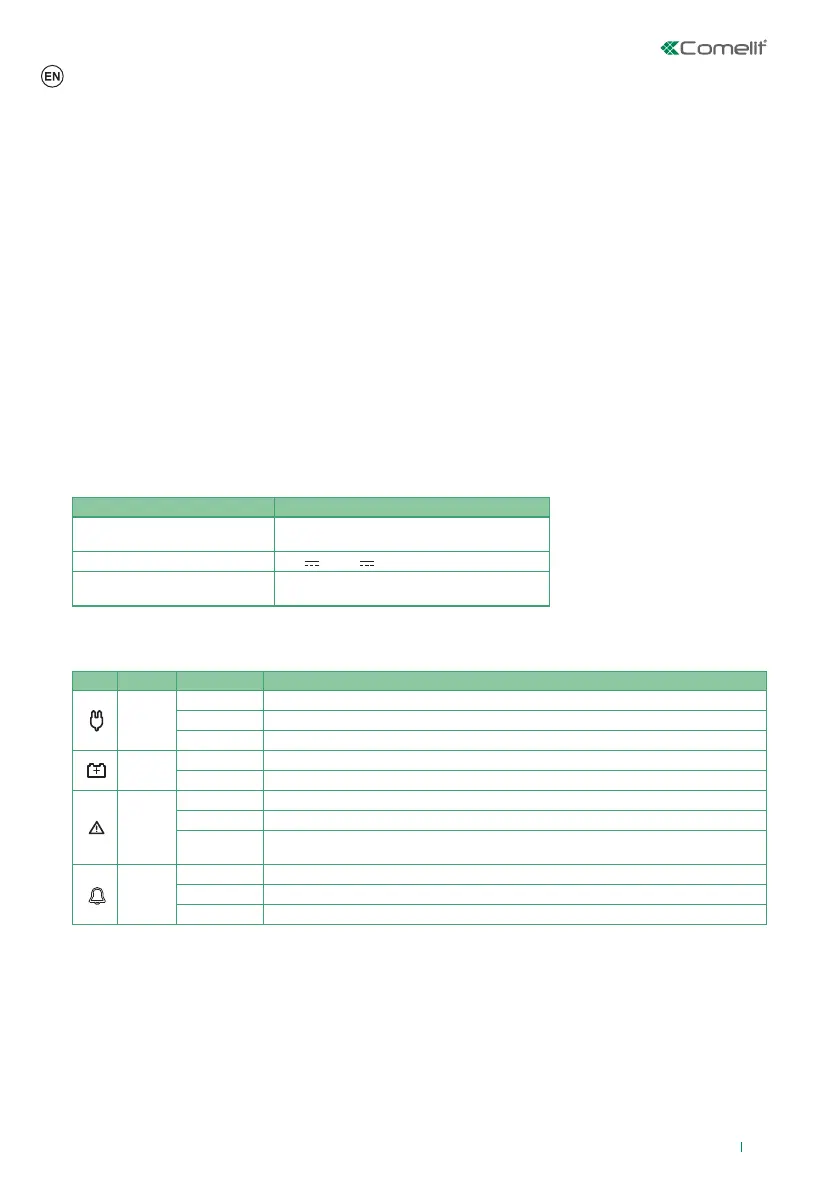
MEANING OF THE KEYPAD LEDS
LED Colour Status Function
Green
O Mains power not present
On Mains power present
Slow fl ash Mains power OK, but system not ready for enabling or there are (non-excluded) open zones
Yellow
O Battery OK
On Indicates an anomaly in the battery of the control panel and/or of a bus power supply unit
Yellow
O No problem
On Problem detected
Slow flash
Presence of isolated, excluded or inhibited zones, or of temporarily excluded anomalies/
sabotages.
Red
O No alarm, sabotage or ongoing fault
On Alarm, sabotage or fault
Slow fl ash Alarm event log, sabotage or fault
DESCRIPTION OF PARTS (FIG. 1)
* the backlighting only comes on in
low light conditions
 Loading...