18
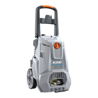
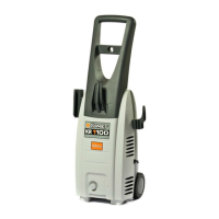
IDENTIFICATION OF COMPONENTS
Refer to Figures 1, 4 and 5.
1. Master switch
2. Identication plate. It indicates the serial
number, guaranteed sound power value (in
compliance with Directive 2000/14/EC) and
main technical specications
3. Warning plate. It informs about residual risks
4. Delivery quick-t coupling
5. Delivery quick-t coupling ring nut
6. Pressure adjustment knob
7. Master switch knob housing
8. Transport handle
9. Wall-xing plugs
10. Washer
11. Screw
12. Upper slots
13. Spray gun
14. Lance hose
15. Nozzle holder head
16. Spray gun lever safety stop
17. Spray gun lever
18. Lower slot
19. Spray gun connection
20. High pressure hose
21. High pressure hose connection (spray gun
side)
22. High pressure hose quick-fit coupling
(pump side)
23. Upper supporting sheet
24. Oil sight glass
25. Pressure indicator
26. Nozzle cleaning pin
27. Feet
28. Power cable
29. Water inlet tting
30. Water inlet lter
31. Water inlet quick-t coupling seal
32. Water inlet quick-t coupling
33. Lower supporting sheet
SAFETY DEVICES
• Ampere cut-out protection device.
This device stops the machine operation in the event of excessive power absorption.
If it trips, proceed as follows:
- move the master switch (1) to “0” position and remove the plug from the power socket;
- press the spray gun (13) lever (17), so as to release any residual pressure;
- wait 10÷15 minutes for the machine to cool down;
- make sure the instructions for connection to the power supply are complied with (refer to
the INSTRUCTION MANUAL - SAFETY WARNINGS), with special reference to the extension
used;
- t the plug back in the socket and repeat the start procedure described in the paragraph
“OPERATION”.
• Pressure unloader/regulation valve
Valve, suitably calibrated by the Manufacturer, for regulating work pressure by means of the
knob (6) and that allows the pumped uid to return to pump suction, thus preventing the onset
of dangerous pressures when closing the spray gun or when trying to set a pressure that is