15
• Guarantee certificate;
• Assistance centres booklet;
• Nozzle cleaning pin.
If there are problems, contact your dealer or an authorised assistance centre.
OPTIONAL ACCESSORIES
The following range of accessories can be added to the standard high-pressure cleaner equipment:
• Sandblasting lance: designed for sanding surfaces, removing rust, paint, incrustations, etc.;
• Pipe flushing probe: designed for unblocking pipes and ducts;
• Rotating nozzle lance: designed for the removal of stubborn grime;
• Foaming lance: designed for a more efficient distribution of detergent;
• Different types of lances and nozzles.
INSTALLATION FITTING OF MOBILE VERSION ACCESSORIES
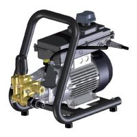
• Insert the handlebar (2) into the steel pipes that protrude from the machine and secure by means of the supplied kit:
screw (9) and retainer (40). SEE FIG. 7
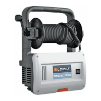
• Insert the holder (7) or the hose reel (12) into the housing hole (41) and secure it with screw (9). SEE FIG. 8.
• If the hose reel is present, connect the quick-fit connector (36) of pipe (42) to the water outlet connector (16) (SEE
FIG. 8)
and fully tighten the ring nut by hand. OPERATION B IN FIG. 9
• If the hose reel is not present, connect the quick-fit connector (36) of pipe (35) to the water outlet connector (16)
(SEE FIG. 2) and full tighten the ring nut by hand. OPERATION B IN FIG. 9
• Screw the high-pressure pipe connector (43) to the thread of the gun (24) and fully tighten with two 22 mm spanners
(not supplied). OPERATION A IN FIG. 9
• Insert the filter (18) into the water inlet connector (17). Insert the seal (26) into the water inlet hose connector (25)
and screw it to the connector (17). OPERATION C IN FIG. 9
PRELIMINARY OPERATIONS
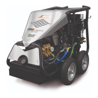
• Place the high-pressure water cleaner in its workstation. The MOBILE version with wheels must be moved using
the handlebar (2). The PICK-UP version must be moved by two people using the handles (27). SEE FIG. 6
• Fully unwind the high-pressure pipe (35).
• Using a flanged clip (not supplied), fix a feed pipe with an internal diameter of 19 mm/0,75 in to the water inlet
hose connector (25). OPERATION C IN FIG. 9.
• Open the mains water supply tap, and make sure there are no drips (or introduce the suction pipe into the tank).
• Check that the master switch (1) is in position “0” and connect the plug. OPERATION D IN FIG. 9
• Place the master switch (1) into position “1”.
• Press the lever (22) of the gun, and wait for a continuous jet of water to exit.
• Place the master switch (1) into position “0”, connect the lance (29) to the gun (24), and tighten it fully. OPERATION E
IN FIG. 9
STANDARD OPERATION (AT HIGH-PRESSURE)
• Check that the nozzle head (30) is not in the detergent distribution position (see also paragraph “OPERATION WITH
DETERGENT”
).
• Start the high-pressure cleaner again, placing the master switch (1) into position “1”.
• Press the lever (22) of the gun, making sure that the jet from the nozzle is even and that there is no dripping.
• If necessary, adjust the pressure by means of knob (8). Turn it clockwise to increase the pressure and anti-clockwise
to decrease the pressure.
• The pressure is indicated on the pressure gauge (13).
OPERATION WITH DETERGENT
The detergents recommended by the manufacturer are over 90% biodegradable.
Refer to the label on the detergent packaging for use instruction.
• Place the master switch (1) into position “0”.
• If aspirating from the high-pressure cleaner’s tank (19), unscrew the cap (11) and taking care not to spill the liquid
(maximum capacity 3.5 l/ 0.92 US gal), fill the tank with detergent, diluted as required.
• In order to clean the detergent tank (19) thoroughly, it can be removed from its location by turning the device (21)
GB

 Loading...
