16
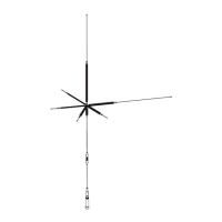
☆ External view of coil installa�on and example of SWR characteris�cs when used with 9 bands
3.5, 7, 14, 18, 21, 28, 50, 144, 430MHz - 9 Bands
1.0
1.5
440 445 450
Freq.(MHz)
1.0
1.5
2.0
145 146 147
Freq.(MHz)
1.0
1.5
2.0
50 52 54
Freq.(MHz)
51
53
1.0
1.5
2.0
21 21.225 21.45
1.0
1.5
2.0
28 29 30
Freq.(MHz)
28.5
29.5
1.0
1.5
18.068 18.110 18.168
Freq.(MHz)
SWR
1.0
1.5
2.0
14 14.175 14.350
Freq.(MHz)
SWR
1.0
1.5
2.0
7 7.10 7.20
Freq.(MHz)
SWR
1.0
1.5
2.0
3.5 3.5375 3.575
Freq.(MHz)
SWR
About moun�ng each element
If it is installed near the horizontally installed antenna
element and parallel to the wall, VSWR may not be
improved.
In that case, try changing the moun�ng posi�on of each
band coil.
Exampleofmountingeachelement [Viewfromabove]
When opera�ng in 9 bands, the lateral
extension of the 7 MHz band element
becomes longer. Please be careful about
contact accidents.
Please note that some bands have difficulty in reducing
SWR due to mutual interference between the bands.
For bands where SWR is hard to improve, we recommend
using an antenna tuner together.
Note : Adjust the SWR of each band to the best possible
condi�on before using the antenna tuner.
3.5MHz Coil (L-3.5)
7MHz Tip element
Element length Approx. 503mm
28MHz Tip element
Element length Approx. 75mm
21MHz Tip element
Element length
Approx. 80mm
18MHz Tip element
Element length
Approx. 75mm
14MHz Tip element
Element length
Approx. 80mm
3.5MHz Tip element
Element length Approx. 503mm
Tip element fixing screw
7MHz Tip element
Side bracket
Element bracket
 Loading...