6
D S - 9 . 5 i
B A T T E R Y
B L A C K ( - )
R E D ( + )
C I R C U I T B R E A K E R ( O P T I O N )
114.3 mm
(4 1/2")
B A T T E R Y
A
F 1
F 2
B L A C K
R E D
B L A C K ( - )
R E D ( + )
C I R C U I T B R E A K E R ( O P T I O N )
S O L E N O I D S
R E M O T E
S W I T C H S O C K E T
W I N C H
Ⅲ
ⅢⅢ
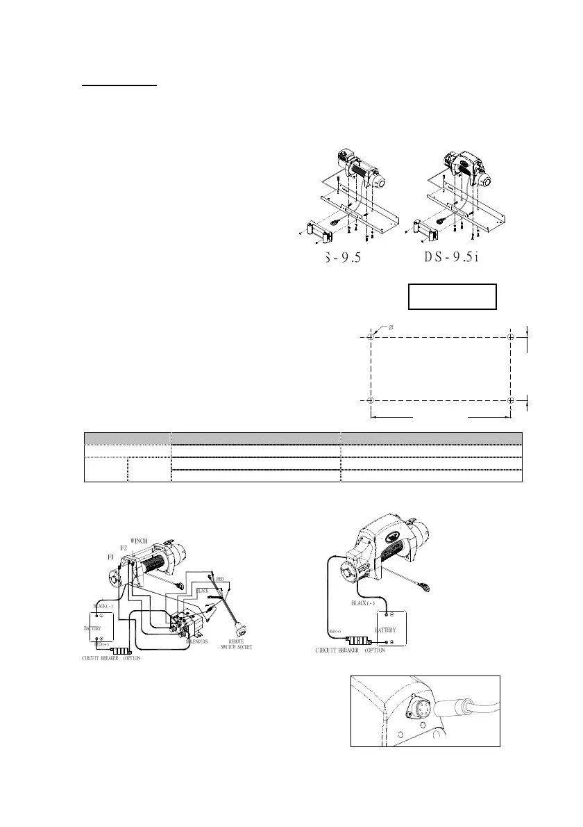
Ⅲ. Installation
Before using the winch, make sure all electrical components have no corrosion or damaged; the
environment should be clean and dry. The voltage drop from the battery connections to the winch
must not exceed 10% of the nominal voltage under normal operating condition.
Mounting
1. It is very important that the winch be
mounted on a flat and hard surface in
order to make sure the motor, drum and
gearbox housing are aligned correctly.
2. It is recommended that you use a
mounting channel to prevent from
damaging winch or vehicle.
3. Four (4) M10 x 1.50 pitch 8.8 Grade High Tensile Steel Bolts must
be used for f
astening the winch into mounting channel in
order to sustain the loads imposed on the winch mounting.
4. Two (2) M12 x 1.75 pitch 8.8 Grade High Tensile Steel
Bolts must be used for fastening the roller fairlead into
the mounting channel.
Battery Lead Connection
Battery lead specification:
Control Type Detachable solenoid pack Integrated solenoid pack
Red cable: 2 AWG x 1.83 m / 72〞 Red cable: 2 AWG x 1.83 m / 72〞
Voltage
12V or
24V
Black cable: 2 AWG x 1.83 m / 72〞 Black cable: 2 AWG x 1.83 m / 72〞
1. Attach the black lead (grounding) firmly to the negative (–) battery terminal.
2. Attach the red lead to the circuit breaker, connect the other end to the positive (+) battery
terminal.
3. The circuit breaker shall be recommended to be fitted.
DS-9.5 DS-9.5i
Switch Connection
1. A trigger switch withψ0.75 mm X 6 C X
5 m (18 AWG X 6 C X 17′) cord supplied
2. Open the dust-proof cover of the winch, then
insert the switch plug into the socket .
Foot print