6
Ⅲ
ⅢⅢ
Ⅲ. Installation
Before using the winch, make sure all electrical components have no corrosion or damaged; the
environment should be clean and dry. The voltage drop from the battery connections to the winch
must not exceed 10% of the nominal voltage under normal operating condition.
Mounting
1. It is very important that the winch
will be mounted on a flat and hard
surface, mounting channel, in
order to make sure the motor,
drum and gearbox housing are
aligned correctly.
2. The roller fairlead doesn’t mount
to winch directly.
3. Four (4) M10 x 1.50 pitch 8.8 Grade High Tensile Steel Bolts must be used for
DV-6000/9000/6000i/9000i in order to sustain the loads imposed on the winch mounting.
4. Eight (8) M12 x 1.75 pitch 8.8 Grade High Tensile Steel Bolts must be used for
DV-12000/15000 in order to sustain the load imposed on the winch mounting.
5. Two (2) M12 x 1.75 pitch 8.8 Grade High Tensile Steel Bolts must be used for fastening the
roller fairlead into the mounting channel.
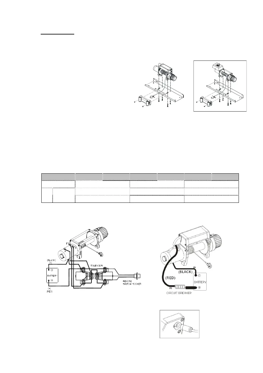
Battery leads connection
Battery leads specification:
Model DV-6000 DV-9000 DV-6000i DV-9000i DV-12000 DV-15000
Control Type Detachable solenoid pack Integrated solenoid pack Detachable solenoid pack
Red lead: 2AWG x 1.83 m/ 72” Red lead: 2AWG x 1.83 m/ 72” Red lead: 2AWG x 1.83 m/ 72”
Volt
12V or 24V
Black lead: 2AWG x 1.83 m/ 72” Black lead: 2AWG x 1.83 m/ 72” Black lead: 2AWG x 1.83 m/ 72”
1. Attach the black lead (grounding) firmly to the negative (–) battery terminal.
2. Attach the red lead to the circuit breaker, connect the other end to the positive (+) battery
terminal.
3. The circuit breaker shall be recommended to be fitted.
CIRCUIT BREAKER (OPTION) (OPTION)
DV-6000/9000/12000/15000 DV-6000i/9000i
Remote control Connection
1. A remote switch withψ1.25 mm X 3c X
5 m (16AWG X 3c X 17’) lead supplied
2. Open the dust-proof cover of the winch, then
insert the switch plug into the socket (fig3).
(Fig3)
DV-6000i / 9000i
DV-12000/15000
 Loading...