Do you have a question about the COMFORT-AIRE Comfort-Cire RAD-121A and is the answer not in the manual?
| Brand | COMFORT-AIRE |
|---|---|
| Model | Comfort-Cire RAD-121A |
| Category | Air Conditioner |
| Language | English |
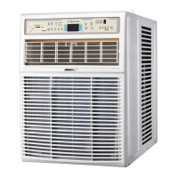
Provides the external measurements of the air conditioner unit.
Guidance on choosing the optimal placement for the air conditioner unit.
Key points to verify after the air conditioner has been installed.
Specifications and preparation needed for window installation.
Steps for preparing the main unit chassis for installation.
Procedure for securely mounting the air conditioner unit into the window.
Details the placement and purpose of all control buttons and indicators.
Instructions for using the remote control to operate the air conditioner.
Guide on properly installing batteries into the remote controller.
Procedures for removing mechanical components of the unit.
Steps for disassembling air handling components like fans and guides.
Instructions for removing various electrical components.
Procedure for removing the overload protector component.
Steps for safely removing the compressor unit.
Procedure for removing the capacitor from the unit.
Steps for removing the thermostat component.
Procedure for removing the rotary switch assembly.
Steps for removing and replacing the power cord.
Procedure for removing the condenser unit.
Steps for removing the evaporator unit.
Procedure for removing the capillary tube.
Diagram illustrating the electrical connections within the unit.
Diagram showing the overall electrical circuit of the unit.
Detailed schematic of the electronic control board and its components.
Layout of components on the main printed wiring board assembly.
Diagram and explanation of the refrigerant piping system.
Diagnostic steps for when the unit operates but does not cool effectively.
Troubleshooting flowchart for units that do not power on or start.
Step-by-step guide for diagnosing unit non-operation.
Troubleshooting steps for compressor failure.
Diagnostic guide for a compressor that runs continuously.
Troubleshooting steps for a non-operational fan.
Steps to diagnose and fix remote control issues.
Troubleshooting guide for display board malfunctions.