As
you will notice, the
A500
and 2000 deletes clocks and interrupt
lines from the A1 000. The
+
l
-
5Vdc and reset lines are also de-
leted. The
+
1
-
12Vdc lines are identical to
a
PC1 0120.
The following signals (formerly on the
RS232 connector) can
be
found
on other
connedors:
ResB
=
parallel connector
C2
=
video connector
Centronics
Port
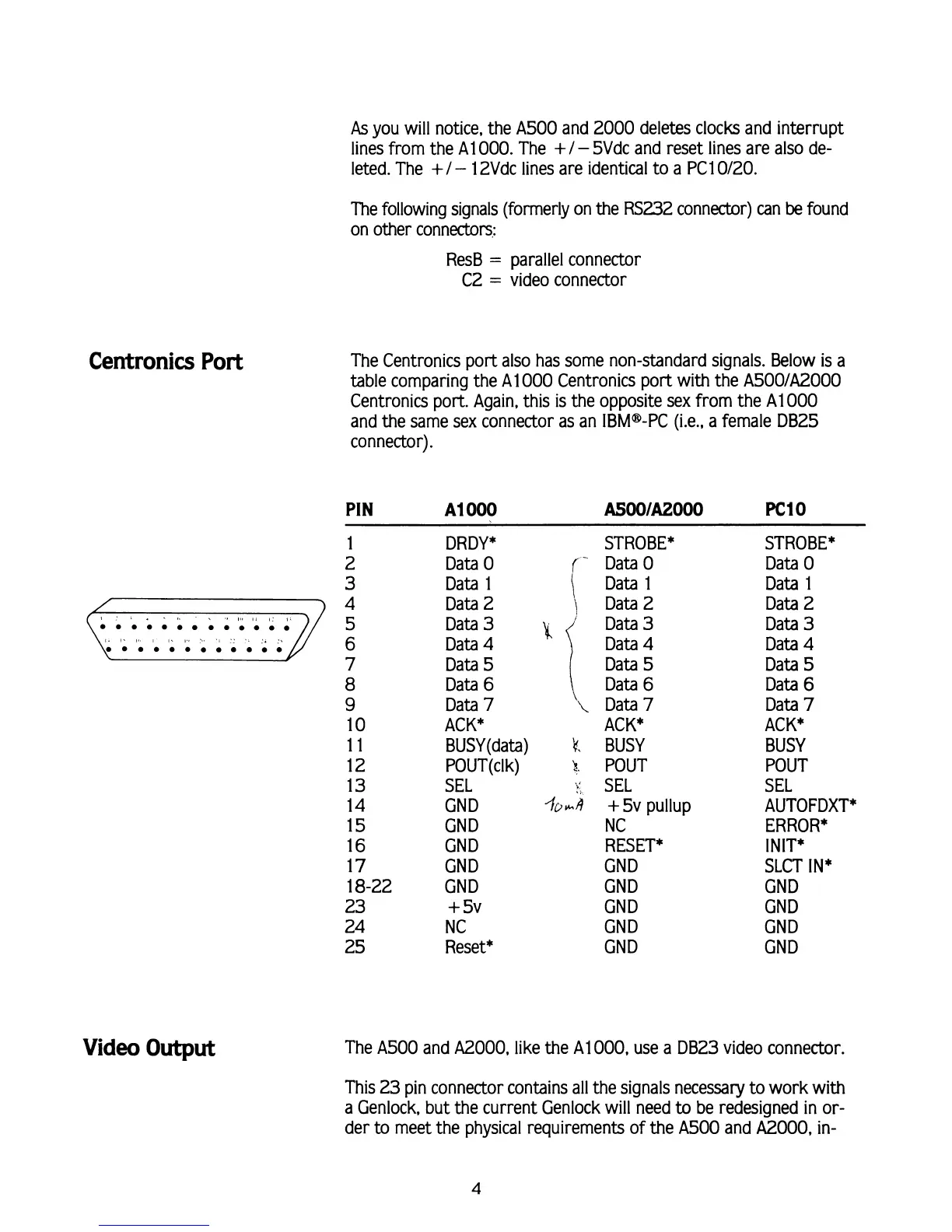
The Centronics port also has some non-standard signals. Below
is
a
table comparing the A1
000
Centronics port with the
A500lA2000
Centronics port. Again, this is the opposite sex from the A1
000
and the same sex connector as an IBMB-PC (i.e., a female DB25
connector).
PIN
A1
000
ASOO/AZOOO
PC1
0
Video
Output
DRDY*
Data
0
Data 1
Data 2
Data
3
Data
4
Data
5
Data
6
Data
7
ACK*
BUSY (data)
POUT(clk)
SEL
CND
CND
CND
CND
GND
+
5v
NC
Reset*
STROBE*
Data
0
\
Data 1
j
Data 2
Data
3
k;
\
\
Data
7
ACK*
k.
BUSY
h
POUT
.
SEL
%*A
+
5v pullup
NC
RESET*
GND
GND
GND
GND
GND
STROBE*
Data
0
Data 1
Data 2
Data
3
Data
4
Data
5
Data
6
Data
7
ACK*
BUSY
POUT
SEL
AUTOFDXT*
ERROR*
INIT*
SLCT
IN*
GND
GND
GND
GND
The
A500
and A2000, like the A1
000,
use a DB23 video connector.
This 23 pin connector contains all the signals necessary to work with
a
Genlock, but the current Genlock will need
to
be redesigned in or-
der to meet the physical requirements of the
A500
and
A2000,
in-