stead of the A1 000. An
A500
genlock will also have to supply
its
own power. Power will not be provided for the Genlock.
All
signals
on the 23 pin connector are the same except for the power.
In addition to the 23 pin video connector, the
A500/B2000 provides
a monochrome composite video output, unlike the A1 000. This pro-
vides the capability of using a low-cost, high persistence mono-
chrome monitor with the
A500
for viewing
640
X
400
interlaced
video without as much flickering.
Power is provided for the A520 modulator and composite video
adapter.
Mouse and Joystick
The mouse and joystick ports of the
A500
and
A2000
are identical
Ports
to the A1
000,
except that the current limiting protection circuitry
has been eliminated. The
A500
and A2000 use a different mouse
than the one the A1 000 uses.
A
diagram and information on this
mouse is included in Appendix
A
of this manual.
Am
mansion Port
The expansion port is electrically compatible with the A1
000,
but be-
cause of
its
physical location,
it
cannot accept any A1 000 expansion
peripherals without some further adapter. Power is supplied to this
connector, but only enough for a ROM cartridge. The exact
pinout of
this
86
pin edge connector appears later in this document, in the sec-
tion of Amiga expansion. The
A500
diagram in Appendix
A
shows the
new positioning of this port (relative to A1
000)
and the pin num-
bers.
Am RAM
mansion
Associated with the built-in 51 2KB of
RAM
is a header socket to al-
low an additional 51
2KB of RAM and a battery backed-up real time
clock board to be added. This small PCB (the
A501 RAM Expansion
Cartridge) can easily be installed by the user. The clock in this unit
functions the same as that built into the
A2000, which is reviewed in
Section 7-1.
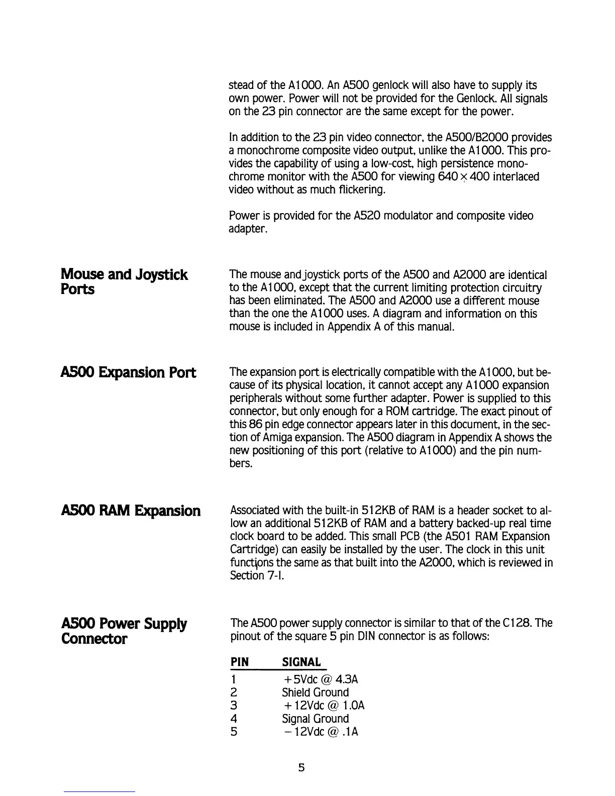
AS00
Power Supply
The
A500
power supply connector is similar to that of the C1 28. The
Connector
pinout of the square
5
pin
DIN
connector is as follows:
PIN
SIGNAL
1
+
5Vdc
@
4.3A
2
Shield Ground
3
+
12Vdc
@
1 .OA
4
Signal Ground
5
-
12Vdc
@
.lA