External
Disk
Interface
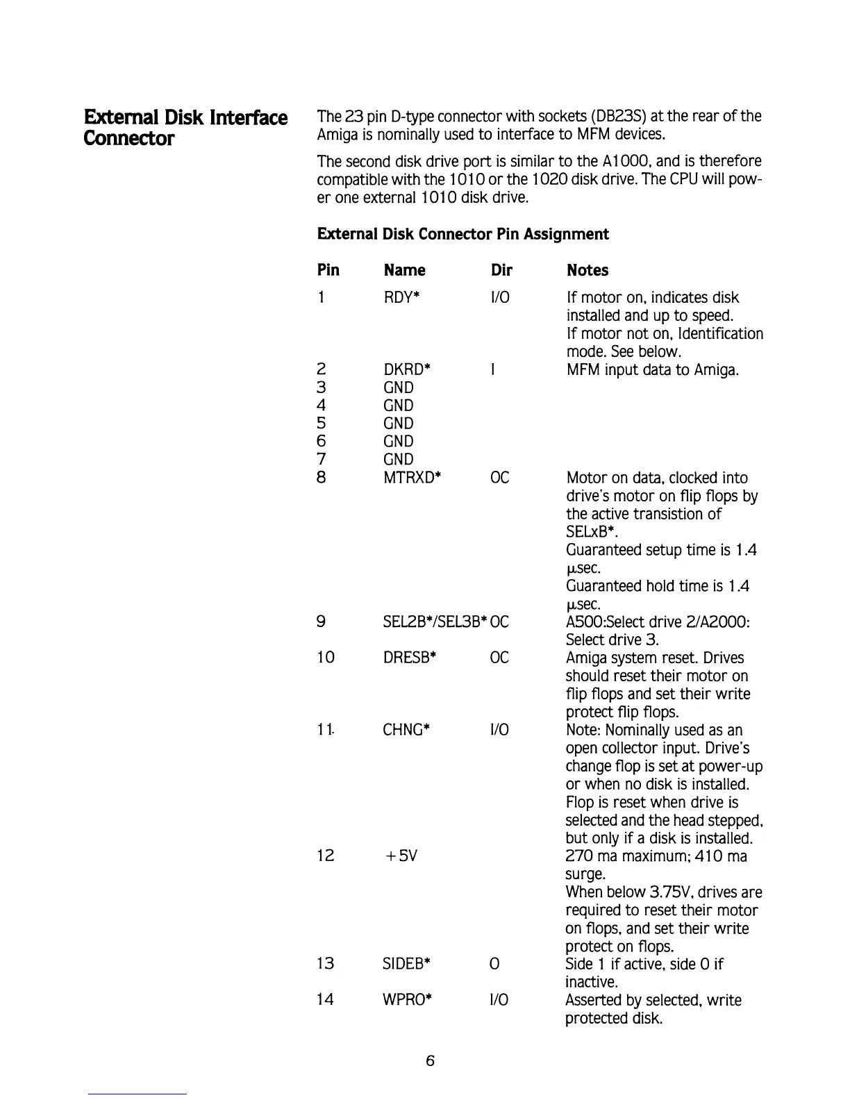
The 23 pin D-type connector with sockets (DB23S) at the rear of the
COM~C~O~
Amiga is nominally used to interface to MFM devices.
The second disk drive port is similar to the
A1 000, and is therefore
compatible with the 101 0 or the 1020 disk drive. The CPU will pow-
er one external 101
0
disk drive.
External Disk Connector Pin Assignment
Pin Name Dir Notes
RDY*
I10
If
motor on, indicates disk
installed and up to speed.
If motor not on, Identification
mode. See below.
DKRD*
I
MFM input data to Amiga.
CND
CND
CND
CND
GND
MTRXD*
13 SIDEB*
14 WPRO*
OC Motor on data, clocked into
drive's motor on flip flops by
the active transistion of
SELxB*.
Guaranteed setup time is 1.4
psec.
Guaranteed hold time is 1.4
psec.
9
SEL2B*/SEL3B* OC A500:Select drive 21A2000:
Select drive 3.
10 DRESB* OC Amiga system reset. Drives
should reset their motor on
flip flops and set their write
protect flip flops.
1 1. CHNG*
110 Note: Nominally used as an
open collector input. Drive's
change flop is set at power-up
or when no disk is installed.
Flop is reset when drive is
selected and the head stepped,
but only
if
a disk is installed.
270 ma maximum; 41 0 ma
surge.
When below
3.75V, drives are
required to reset their motor
on flops, and set their write
protect on flops.
0
Side 1
if
active, side 0 if
inactive.
I10 Asserted by selected, write
protected disk.