AMlGA 110 MEMORY MAP
(REGISTER DESCRIPTION)
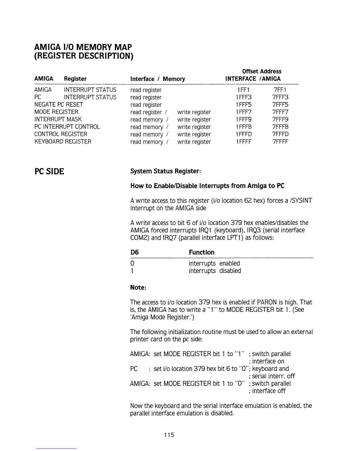
AMlGA Register
AMlGA INTERRUPT STATUS
PC INTERRUPT STATUS
NEGATE PC RESET
MODE REGISTER
INTERRUPT MASK
PC INTERRUPT CONTROL
CONTROL REGISTER
KEYBOARD REGISTER
PC SIDE
Interface
1
Memory
Offset Address
INTERFACE
IAMIGA
read register
read register
read register
read register
I
write register
read memory
l
write register
read memory
I
write register
read memory
I
write register
read memory
1
write register
l
FFl
1
FFF3
1
FFFS
1
FFF7
1
FFF9
l
FFFB
l
FFFD
l
FFFF
System Status Register:
How to
EnableIDisable Interrupts from Amiga to
PC
A
write access to this register (i/o location 62 hex) forces a ISYSINT
interrupt on the AMlGA side
A write access to bit
6
of i/o location
379
hex enablesldisables the
AMIGA forced interrupts
IRQl (keyboard), IRQ3 (serial interface
COM2) and IRQ7 (parallel interface LPT1) as follows:
D6 Function
interrupts enabled
interrupts disabled
Note:
The access to i/o location
379
hex is enabled if PARON is high. That
is,
the AMlGA has to write a "1
"
to MODE REGISTER bit 1. (See
'Amiga Mode Register.')
The following initialization routine must be used to allow an external
printer card on the pc side:
AMIGA: set MODE REGISTER bit 1 to
"1"
;
switch parallel
;
interface on
PC
:
set ilo location
379
hex bit
6
to
"0";
keyboard and
;
serial interr. off
AMIGA: set MODE REGISTER bit
1
to
"0"
;
switch parallel
;
interface off
Now the keyboard and the serial interface emulation is enabled, the
parallel interface emulation
is
disabled.