How to Clear
an
Asserted Interrupt
Signal
INT Negation
I
RQ3-a Read to ilo location 3b0 hex
I
RQ3-b
Read com2 register 2F8 hex
I
RQ7
Read line printer status register
379
hex
IWMA SIDE
All registers on the memory locations 1 FFFO TO 1 FFFF are only
accessable from the
AMIGA side.
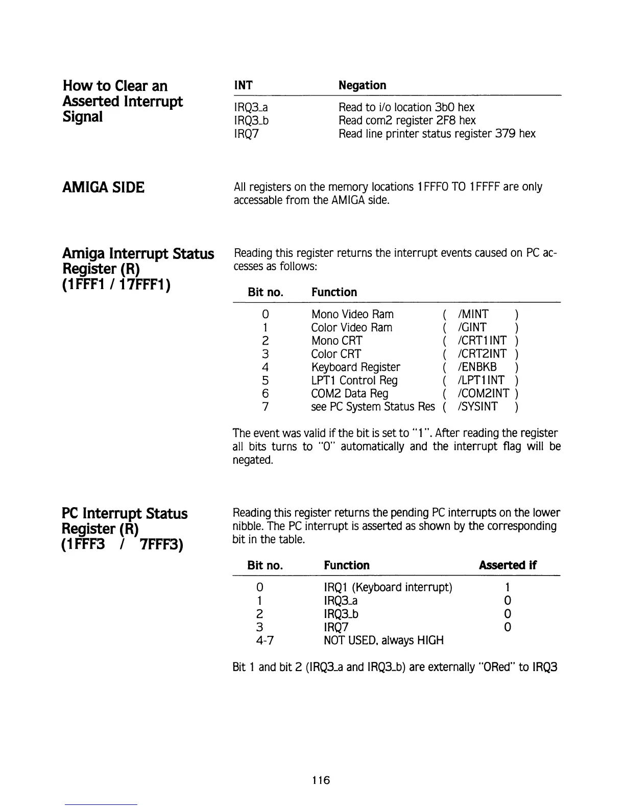
Amiga Interrupt Status
Reading this register returns the interrupt events caused on PC ac-
Register
(R)
cesses as follows:
(1
FFFI
1
1
7FFF1)
Bit no. Function
PC
Interrupt Status
Register
(R)
(1FFF3
/
7FFF3)
0
Mono Video Ram
1
Color Video Ram
(
2 Mono CRT
(
(
3
Color CRT
4
Keyboard Register
(
5
LPTl Control Reg
(
COMZ Data Reg
(
6
7
(
see PC System Status Res
(
/MINT
)
/GINT
)
ICRT1 INT
)
/CRT21NT
)
IENBKB
)
ILPT1 INT
)
ICOMZINT
)
ISYSINT
)
The event was valid if the bit
is
set to "1
".
After reading the register
all bits turns to
"0"
automatically and the interrupt flag will be
negated.
Reading this register returns the pending PC interrupts on the lower
nibble. The PC interrupt
is
asserted as shown
by
the corresponding
bit in the table.
Bit no. Function
Asserted
if
0
IRQ l (Keyboard interrupt) 1
1
I
RQ3-a
0
2
I
RQ3-b
0
3
I
RQ7
0
4-7
NOT
USED,
always HIGH
Bit
1 and bit 2 (IRQ3-a and IRQ3-b) are externally "ORed" to IRQ3