Blitter
The priority control logic looks at the pipe-lined DMA requests from
each controller and stages the DMA cycles based upon their pro-
grammed priority and sync counter time slot. Then
it
signals the pro-
cessor to get off the bus by asserting the DBR line.
The following
is
a brief description of the device's major operational
modes.
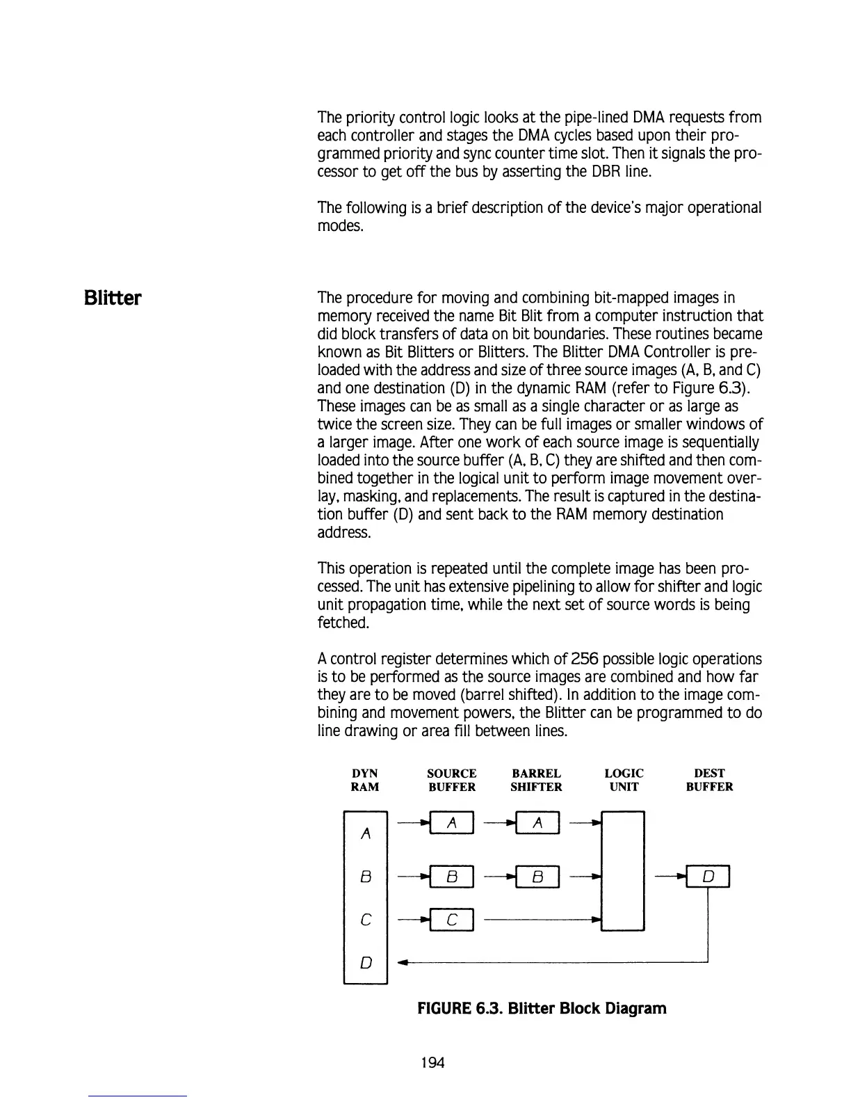
The procedure for moving and combining bit-mapped images in
memory received the name
Bit Blit
from a computer instruction that
did block transfers of data on bit boundaries. These routines became
known as Bit Blitters or Blitters. The Blitter DMA Controller is
pre-
loaded with the address and size of three source images
(A,
B, and C)
and one destination (D) in the dynamic RAM (refer to Figure
6.3).
These images can be as small as a single character or as large as
twice the screen size. They can be full images or smaller windows of
a larger image. After one work of each source image
is
sequentially
loaded into the source buffer
(A,
B,
C) they are shifted and then com-
bined together in the logical unit to perform image movement over-
lay, masking, and replacements. The result is captured in the destina-
tion buffer (D) and sent back to the RAM memory destination
address.
This operation
is
repeated until the complete image has been pro-
cessed. The unit has extensive pipelining to allow for
shifter and logic
unit propagation time, while the next set of source words
is
being
fetched.
A
control register determines which of
256
possible logic operations
is to be performed as the source images are combined and how far
they are to be moved (barrel shifted). In addition to the image com-
bining and movement powers, the Blitter can be programmed to do
line drawing or area fill between lines.
DYN
SOURCE BARREL
LOGIC DEST
RAM BUFFER
SHIFTER UNIT BUFFER
FIGURE
6.3.
Blitter Block
Diagram
1
94