read sequence.
All
TOD registers latch on a read of MSB event and
remain latched until after a read of LSB Event. The TOD clock contin-
ues to count when the output registers are latched. If only one regis-
ter is to be read, there is no carry problem and the register can be
read "on the fly", provided that any read of MSB Event is followed
by a read of LSB Event to disable the latching.
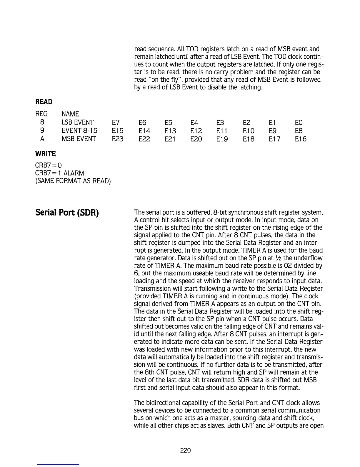
READ
REG NAME
8
LSB EVENT
E7
E6
E5
E4
E3
E2
E
l E0
9
EVENT8-15 E15 E14 E13 E12 El 1 E10 E9 E8
A MSBEVENT E23 E22 E21 E20 E19 E18 E17 E16
WRITE
CRB7
=
0
CRB7= 1 ALARM
(SAME FORMAT AS READ)
Serial
Port
(SDR)
The serial port is a buffered, 8-bit synchronous shift register system.
A
control bit selects input or output mode. In input mode, data on
the SP pin is shifted into the shift register on the rising edge of the
signal applied to the CNT pin. After
8
CNT pulses, the data in the
shift register
is
dumped into the Serial Data Register and an inter-
rupt
is
generated. In the output mode, TIMER A is used for the baud
rate generator. Data is shifted out on the SP pin at
'/z
the underflow
rate of TIMER A. The maximum baud rate possible
is
02 divided by
6,
but the maximum useable baud rate will be determined by line
loading and the speed at which the receiver responds to input data.
Transmission will start following a write to the Serial Data Register
(provided TIMER
A
is
running and in continuous mode). The clock
signal derived from TIMER
A
appears as an output on the CNT pin.
The data in the Serial Data Register will be loaded into the shift reg-
ister then shift out to the SP pin when a CNT pulse occurs. Data
shifted out becomes valid on the falling edge of CNT and remains val-
id until the next falling edge. After
8
CNT pulses, an interrupt
is
gen-
erated to indicate more data can be sent.
If
the Serial Data Register
was loaded with new information prior to this interrupt, the new
data will automatically be loaded into the shift register and transmis-
sion will be continuous.
If
no further data
is
to be transmitted, after
the
8th
CNT pulse, CNT will return high and SP will remain at the
level of the last data bit transmitted. SDR data
is
shifted out MSB
first and serial input data should also appear in
this
format.
The bidirectional capability of the Serial Port and CNT clock allows
several devices to be connected to a common serial communication
bus on which one acts as a master, sourcing data and shift clock,
while all other chips act as slaves. Both CNT and SP outputs are open