860660202 Rev. B www.commscope.com
Instruction Sheet
© 2021 CommScope, Inc. All Rights Reserved Page 5 of 9
3. Cut the insulated power conductors to length. Strip off 5mm of insulation from the
conductors using an electrical wire stripper (12 AWG – 2.0mm; 14 AWG –1.6mm; 16 AWG –
1.3mm; 18 AWG -1.0 mm; 20 AWG– 0.8mm; 22 AWG – 0.65mm; 24 AWG – 0.5mm).
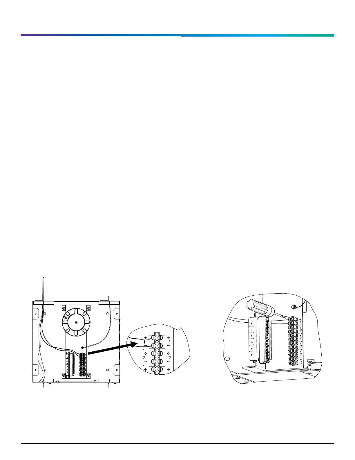
4. Match the wire polarity from the cable plant with the terminal strip polarity, as shown in
Figure 6.
5. Using a small flat screwdriver open the screw terminals until the wires insert into the
terminal ports. Push each wire into its port. Screw each terminal down hand tight to make
contact between the terminal and the wire conductor. Verify the wires are secure in the
terminals with no exposed wire conductor, as shown in Figure 7.
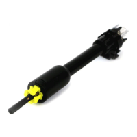
6. Terminate the LC Fiber Optic plugs (see section 2) per the product specifications instructions. Visit
www.commscope.com for LC Connector application, instructions, and tool kit information.
7. Clean and install the LC terminations into the adapter; see installation and cleaning instructions:
TECP-96-194. Store excess fiber on the spool, as shown in Figure 8.
8. Repeat steps 1 – 5 for all incoming PFCs.