860660202 Rev. B www.commscope.com
Instruction Sheet
© 2021 CommScope, Inc. All Rights Reserved Page 3 of 9
5. Installation steps
Step 1 – Mounting and Grounding the Transition Box (TB)
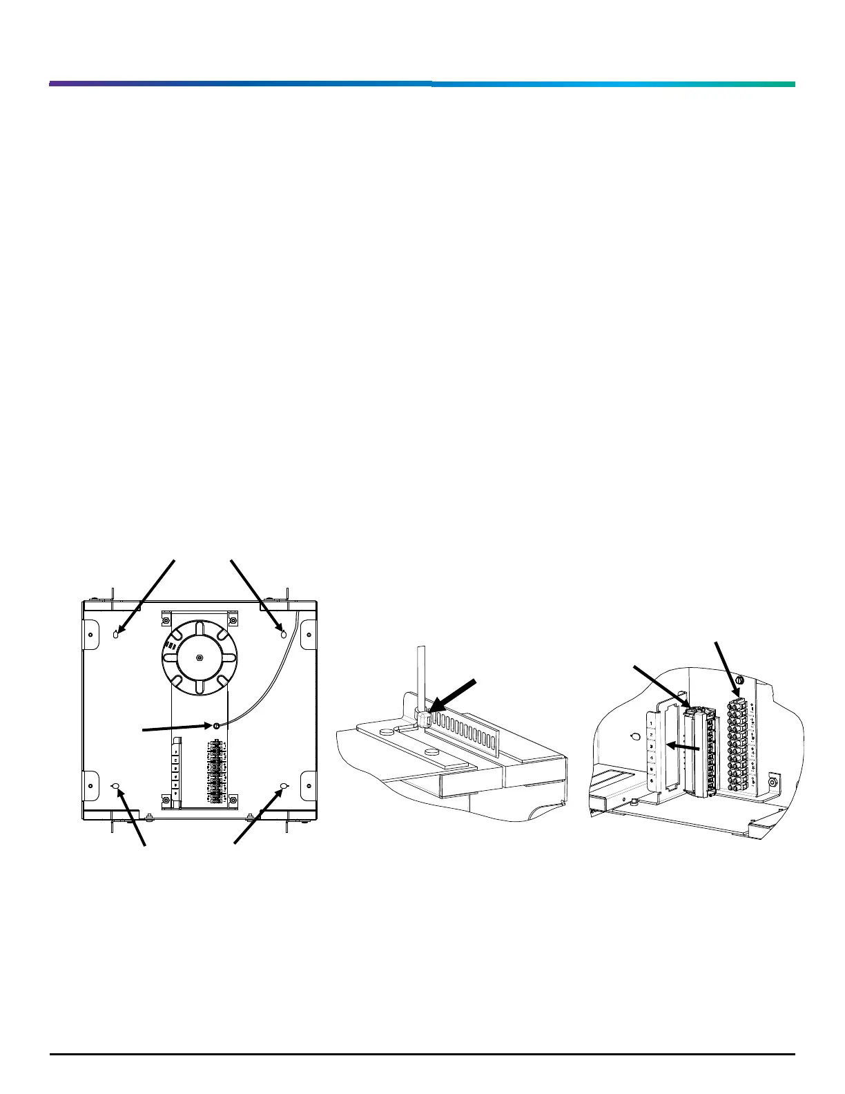
1. Mount the TB to a flat surface using the four mounting knockouts as shown in Figure 1.
Note: Customer provided installation hardware must match the intended application with a
minimum pull-out requirement of 20 lbs-f (88 N) per hardware location.
2. Attach 12 AWG (or larger) ground wire to the TB using the green ground screw as shown in Figure
1. Attach wire to Earth ground.
3. Secure the ground wire to the strain relief bar with a supplied cable tie as shown in Figure 2.
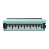
4. Insert the 6 port fiber adapter into the G2 opening with the shutters facing in the direction of the
terminal strip, as shown in Figure 3.
Figure 1 Figure 2 Figure 3