Do you have a question about the CommScope RUCKUS ICX 7550 and is the answer not in the manual?
Explains how notes, cautions, and warnings are used to convey potential hazards.
Details text conventions used for command syntax elements like bold and italics.
Highlights changes and updates in the current version of the manual.
Lists the supported Ruckus ICX 7550 switch models and software versions.
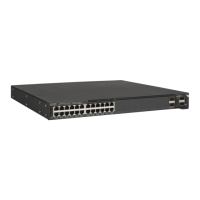
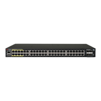
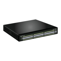
Details the hardware capabilities and features of the RUCKUS ICX 7550 switch.
Illustrates and labels the components on the port-side of the ICX 7550 switch.
Illustrates and labels the components on the nonport-side of the ICX 7550 switch.
Provides essential safety warnings and guidelines before installation.
General safety advice applicable to the installation process.
Specific precautions for preventing electrostatic discharge damage.
Crucial safety measures related to power connections and handling.
Safety guidelines for lifting and mounting the device considering its weight.
Safety warnings regarding laser radiation from fiber-optic interfaces.
Specifies the environmental and site requirements for installation.
Provides high-level checklists for a smooth installation process.
Details essential tasks to perform before the actual installation.
Covers various options for physically installing the device.
Ensures all necessary items are ready before starting the setup.
Instructions on how to connect power to the installed device.
Steps for initial console connection and basic security setup.
Guides on configuring network addressing for device management.
Procedure for configuring the device's date and time settings.
Instructions for setting unique host and chassis names for identification.
Details on connecting to the dedicated management port for configuration.
Describes the various methods available for mounting the device.
Critical safety guidelines specifically for mounting the device.
Procedure for safely removing port covers before installation.
Instructions for installing the device on a flat surface like a desk.
Guide for installing the device in a two-post rack using the ICX7000-RMK kit.
Instructions for mounting in a two-post rack using the ICX-RMK-4POST-TL kit.
Details the process for flush-mounting the device in a rack.
Guide for installing the device in a four-post rack using the ICX-RMK-4POST-TL kit.
Step-by-step instructions for flush-mounting the device in a rack.
Instructions for mounting the device recessed in a rack.
Outlines the prerequisites for configuring devices in a stack.
Illustrates various ways ICX 7550 devices can be connected in a stack.
Important considerations and notes for setting up device stacking.
Details stacking and uplink capabilities for Module 2.
Information on compatibility between Module 2 and Module 3 configurations.
Lists the necessary hardware and software for initial setup.
Steps for safely powering on the device after installation.
Guide for establishing an initial connection via the console port.
Procedure to reset the device to its factory default configuration.
Steps to regain access if a device password is lost.
Instructions for assigning an IP address for network management.
How to set unique host and chassis names for device identification.
Procedure to configure the device's date and time.
Details for connecting via the out-of-band management port.
Methods to confirm the device is functioning correctly after setup.
Instructions on how to save the current device configuration.
Lists the time and components needed for transceiver installation.
Safety guidelines for handling transceivers and cables.
Recommendations for organizing and managing network cables.
Steps for connecting Ethernet RJ-45 cables to the device.
Procedure for cleaning fiber-optic connectors to ensure performance.
Instructions for installing fiber-optic transceivers into the device.
Steps for correctly connecting cables to fiber-optic transceivers.
Guide for replacing an existing fiber-optic transceiver.
Details on the LRM adapter module for specific fiber optic transceivers.
Lists the available part numbers for the LRM adapter module.
Explains the meaning and status of port-side LEDs on the switch.
How to use the status mode button to view different LED statuses.
Details the STAT LED for indicating port link status and activity.
Explains the SPD LED for indicating port speed status.
Details the ID LED for indicating the stack member ID.
Explains the USB LED status for file transfer operations.
Details the PoE LED status for Power over Ethernet ports.
Explains the SYS LED for indicating the overall system status.
Details the MS LED for indicating master/slave status in stacking.
Explains the UPDATE LED status for software installation.
Details the DIAG LED status for system self-diagnostic tests.
Explains the LED status for cloud or on-premise management.
Details the PWR LEDs for indicating power supply status.
Explains the meaning of LEDs on the nonport-side (rear) panel.
Provides tables detailing the patterns and meanings of various LEDs.
How to use ping to verify network connectivity to a device.
Guidance on monitoring device temperature and power status.
Lists the temperature limits for device operation and shutdown.
Introduces the types of power supplies supported by the ICX 7550.
Critical safety warnings and precautions for handling power supplies.
How to identify the correct airflow direction for power supplies and fans.
Instructions for replacing a faulty power supply unit.
Step-by-step guide for installing a new AC power supply.
Procedure for installing the AC power cord strain relief strap.
Step-by-step guide for installing a new DC power supply.
Instructions for properly grounding the switch chassis.
Details on the types of grounding lugs available for the terminal.
Steps for making the electrical connection to the grounding terminal.
Introduces the redundant, hot-swappable fan assemblies.
Critical safety warnings and precautions for handling fan assemblies.
How to identify the correct airflow direction for fan assemblies.
Step-by-step guide for installing a new fan assembly.
Introduces the supported media expansion modules for the switch.
Critical safety warnings and precautions for handling expansion modules.
Instructions for installing or replacing expansion modules.
Guidance on resolving configuration mismatches with Module 3.
Provides an overview of the system's general specifications.
Details the Ethernet port specifications and counts for various models.
Lists the types of LEDs and their functions on the switch.
Provides dimensions and weight details for each switch model.
Specifies operational and non-operational environmental conditions.
Details the specifications for each individual power supply unit.
Shows power consumption figures for typical operating conditions.
Shows power consumption figures for maximum load conditions.
Details the specifications for Ethernet data ports and modules.
Pinout details for the USB Type-C serial port.
Pinout details for the RJ-45 serial port.
Details the memory types and capacities of the switch.
Lists electromagnetic compatibility compliance standards.
Lists safety compliance standards and certifications.
Lists environmental compliance standards and regulations.
Provides regulatory compliance statements for different regions.
FCC compliance statement and warning for US users.
Statement regarding Canadian interference-causing equipment regulations.
Class A warning for Europe and Australia regarding potential radio interference.
VCCI compliance statement for Japanese users.
KCC compliance statement for Korean users.
China CCC compliance statement and warnings.
BSMI compliance statement for Taiwan.
General cautions to be observed during operation and maintenance.
Broad safety advice applicable to the device.
Specific safety warnings related to electrical hazards.
Notifications of potential hazards that could cause injury or death.
General warnings about potentially lethal hazards.
Warnings related to the physical weight of the equipment.
Safety warnings concerning laser radiation from optical interfaces.
| Model | ICX 7550 |
|---|---|
| Redundant Power Supplies | Yes |
| Redundant Fans | Yes |
| Stacking | Up to 12 switches |
| Operating System | RUCKUS FastIron |
| 100GbE Ports | Dependent on module configuration |
| 40GbE Ports | Dependent on module configuration |
| 25GbE Ports | Dependent on module configuration |
| 10GbE Ports | Dependent on module configuration |
| Operating Temperature | 32°F to 104°F (0°C to 40°C) |
| Storage Temperature | -40°C to 70°C (-40°F to 158°F) |
| Humidity | 5% to 95% RH, non-condensing |
| AC Power Input | 100-240VAC, 50/60 Hz |