EasyManua.ls Logo

Comnet Copper Line CLFE1EOU - User Manual

Comnet Copper Line CLFE1EOU
12 pages
Print Icon
To Next Page IconTo Next Page
Loading...
INS_CLFE(X)EO(C,U)_REV– 10/27/11 PAGE 1TECH SUPPORT: 1.888.678.9427
INSTALLATION AND OPERATION MANUAL
CLFE(X)EO(C,U) Series
ETHERNET OVER COPPER EXTENDER
WITH PASS-THROUGH POE TO 15 WATTS
The ComNet
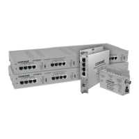
CopperLine® Ethernet over copper line supports up to sixteen
channels of 10/100Mbps Ethernet with Pass-through PoE over twisted pair cable
(CAT-5, UTP), or over coaxial cable. The single channel units may be powered by a
PoE switch or the included power supply. Four, eight, and sixteen channel units
operate from local power. These units provide the ultimate flexibility for extending
a powered device (PD) over long distance copper. DIP switches are provided for user-
selection of local or remote, 10 or 100Mbps, and 1 pair or 4 pair (UTP) settings.
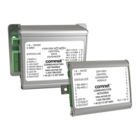
Bi-color (Red/Green) LED indicators are provided for rapidly ascertaining equipment
operating status. Table 2 on Page 9 describes the LED indicators for each light on
the unit.
The CLFE8EO(C,U) and CLFE16EO(C,U) are 1RU rack mountable units. The
CLFE4EO(C,U) units are interchangeable between stand-alone or card mount
configurations, or may be DIN-rail mounted by the addition of ComNet model
DINBKT1 or DINBKT4 adaptor plate. The CLFE1EO(C,U) units are stand-alone, or
may be DIN-rail mounted by the addition of ComNet model DINBKT4 adaptor. See
Figures A through C on Page 11 for mounting instructions.
This manual serves the following
ComNet Model Numbers:
CLFE1EOC
CLFE4EOC
CLFE8EOC
CLFE16EOC
CLFE1EOU
CLFE4EOU
CLFE8EOU
CLFE16EOU
Question and Answer IconNeed help?

Do you have a question about the Comnet Copper Line CLFE1EOU and is the answer not in the manual?

Summary

Single Channel Unit Diagrams and Controls

CLFE1 EOC Coax Unit Diagram

Illustrates the CLFE1EOC coax unit's physical layout and connections.

CLFE1 EOU UTP Unit Diagram

Details the CLFE1EOU UTP unit's physical layout and connections.

Four Channel Coax Unit Diagrams

CLFE4 EOC Coax Unit Diagram

Shows the CLFE4EOC coax unit's physical layout and connections.

Four Channel UTP Unit Diagrams

Eight Channel Unit Diagrams

Sixteen Channel Coax Unit Diagrams

Sixteen Channel UTP Unit Diagrams

Installation Instructions and Configuration

DIP Switch and Port Configuration

Guides on setting data rate, wire pair, and local/remote switches for optimal operation.

Powering and Verifying Operation

Explains power connection requirements and how to interpret status LEDs.

Comnet Copper Line CLFE1EOU Specifications

General IconGeneral
CategoryExtender
ModelCLFE1EOU
Data Rate10/100 Mbps
Copper InterfaceRJ45
Humidity5% to 95% non-condensing
TypeEthernet Extender
DistanceUp to 1.2km (4, 000 feet)
Operating Temperature-40°C to 75°C

Related product manuals