6. Preparations for commissioning
26
6 Preparations f or commissioning
6.1 Cooling air volume/minimum cross
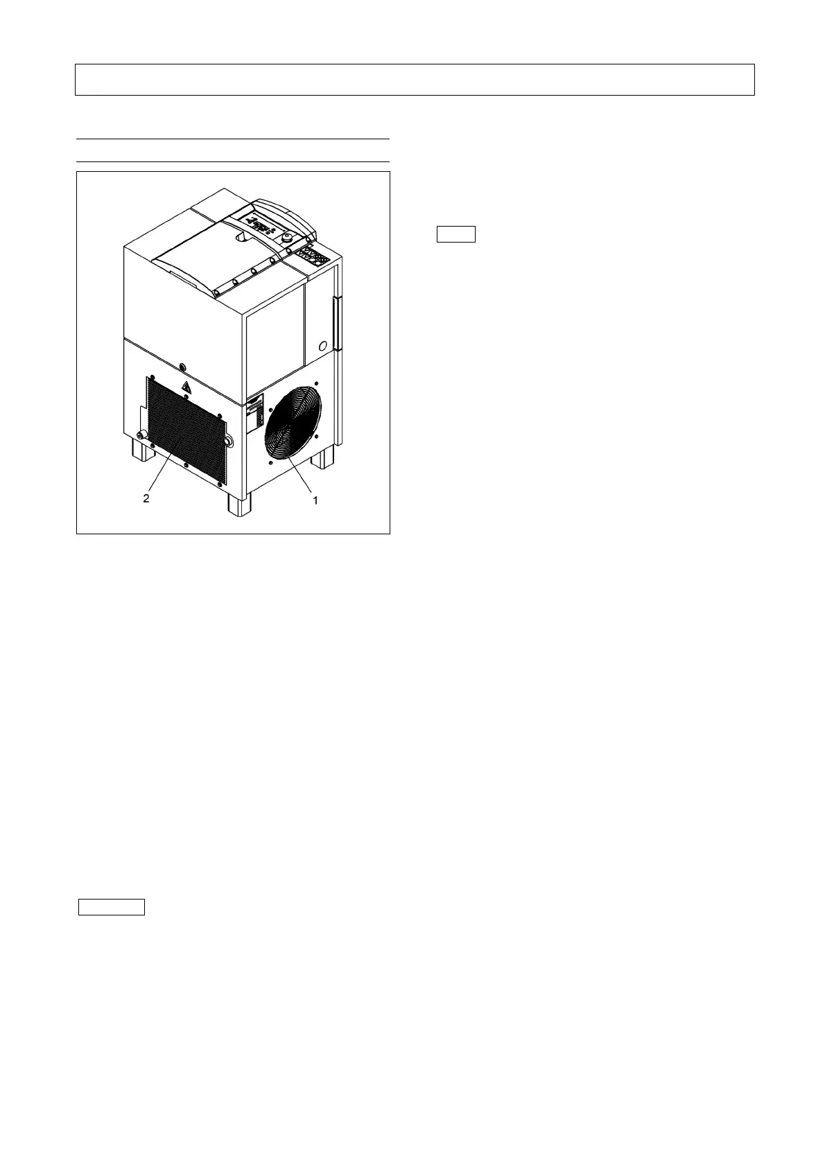
Fig. 8
1 Cooling air intake
2 Cooling air outlet
The cooling air volume required by these screw
compressors is as follows:
50-Hz-compressors:
L07 approx. 25 m
3
/min
L11 approx. 32 m³/min
60-Hz-compressors:
L07 approx. 30 m
3
/min
L11 approx. 34 m³/min
Speed-controlled compressors 50 Hz/ 60 Hz:
L07RS approx. 25 m
3
/min
L11RS approx. 32 m³/min
Under unfavourable local conditions, we recommend
the installation of venting ducts. However, the velocity
of the cooling air should not exceed 5 m/s. We
recommend a minimum duct cross-section of approx.
0.2 m
2
for L07-L11.
Important
The stated minimum cross-section refers to a
maximum duct length of 5 m/16.4 ft and a maximum
of one bend. In the event of differing values (over
5 m/16.4 ft, more than one bend, filter cartridges,
screens, etc.), please contact your technical
adviser.
CompAir screw compressors are rated for ambient
temperatures and cooling temperatures of +1°C/
33.8°F to +45°C/113°F. In the case of temperatures
other than the above limiting values, please consult
your technical adviser.
Note
In order to ensure a good heat dissipation, auxiliary
fans should be rated to process approximately 15 to
20% more air volume than the total cooling air
quantity required by the compressors installed in the
compressed air station.