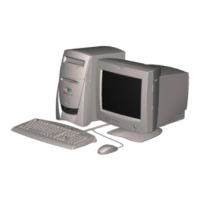
6. Now remove the rear set of keyboard screws. These are located in the middle of the
bottom of the LTE.
7. You should now have all the keyboard screws removed. Collect all of the screws you
removed (there should be seven screws) and flip the LTE back over. Place it so the ports
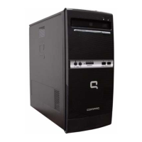
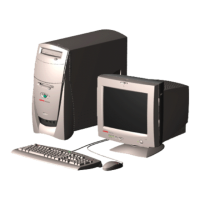
are now facing you. You are now going to remove the screws that secure the top cover
with power switch and standby buttons on it. Locate the screws in the upper area of each
corner near the display panel and remove them. There is also a single screw behind the
status indicator display. Remove this as well. You will now have three more screws to set
aside.
Do NOT remove the lower screws. These actually secure the display panel and
unless you are servicing the panel itself, I would strongly suggest you leave them
alone.
8. With all three screws removed, open the display panel, making sure to open the latches
on the side fully. (The keyboard is still pretty firmly attached, so it is unlikely that you'd
 Loading...