6 R
EPLACING AN
E
XPANSION
C
ARD
You do not have to replace the
screw securing the side access
panel. The screw securing the
side panel is used for shipping
purposes only.
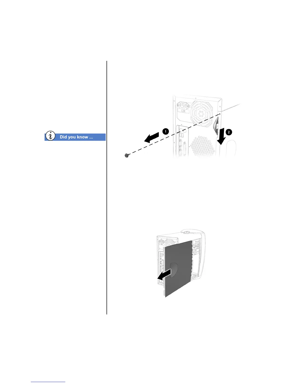
II. Opening the Side Access Panel
1. Remove the screw 1 securing the side access panel.
Locate the latch 2 directly below the screw, press down,
and hold in the down position (see Figure 2-1).
Figure 2-1
Important: Some models may not have a screw 1
. This screw is used
for shipping purposes only.
2. Grab the handle and slide the side panel from the chassis
(see Figure 2-2).
▲
Caution: Before doing any work inside your computer, ground
yourself by touching a metal part of the chassis.
Figure 2-2
 Loading...