Pin 3 Orange/Black – 2
nd
Pulse Unlock wire. This wire is used to provide the customer with a driver’s
priority unlock feature with option 1-04. With the option on the unlock (blue) wire will pulse first
and then orange/black will pulse if the unlock button is pressed again within 3 seconds.
Pin 4 Blue - Unlock 250mA negative (-) output. This is an optional output that will provide a (-) pulse for
unlocking doors. System will unlock doors. IMPORTANT: You must use relays to reverse
polarity for (+) trigger door lock systems.
Pin 5 Blue/Black - Lock 250mA (-) negative output. This is an optional output that will provide a (-)
pulse for locking doors. System will lock doors. IMPORTANT: You must use relays to reverse
polarity for (+) trigger door lock systems.
Pin 6 Not used
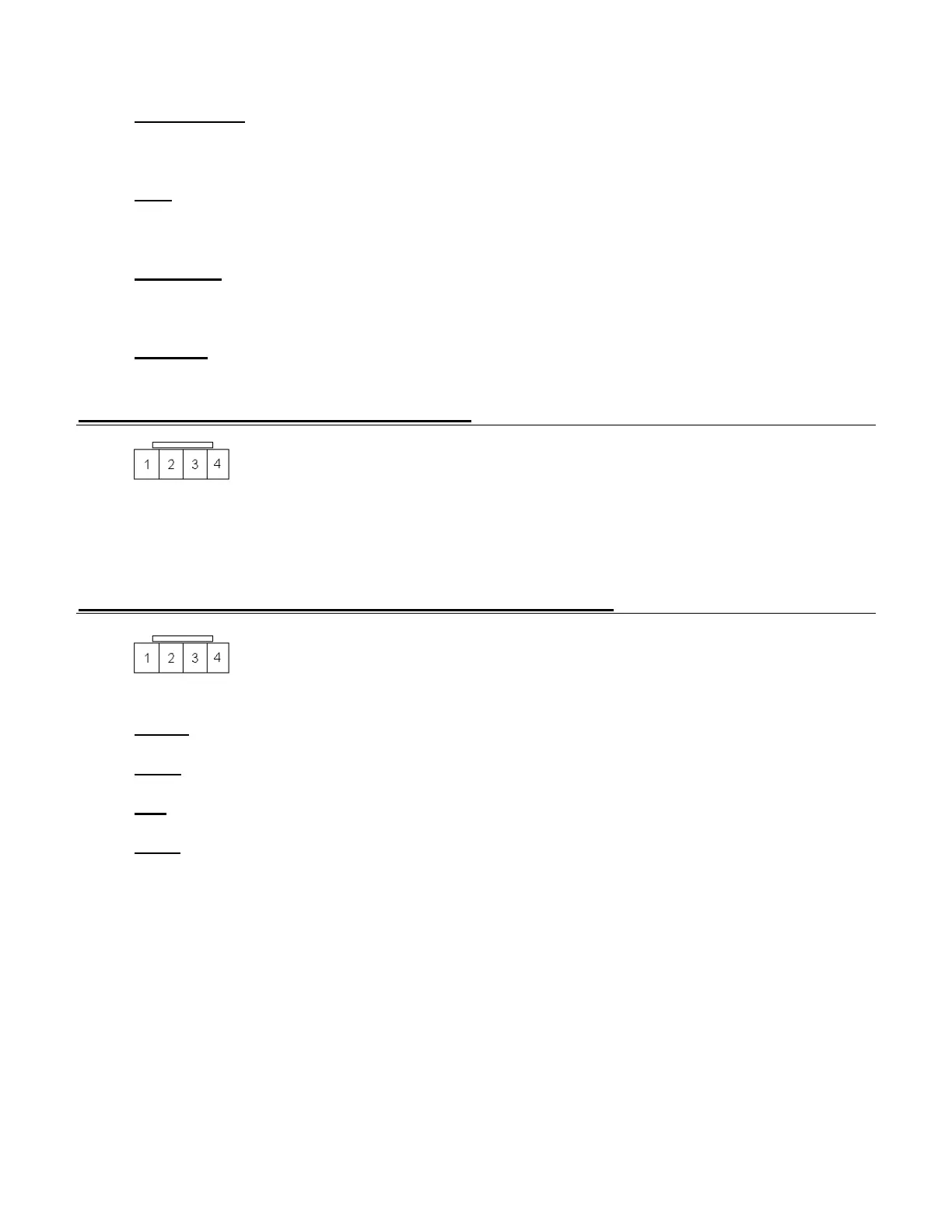
Connector 4 (CN4), 4-Pin (RS232 Port)
This port provides simple connectivity to iDataLink bypass modules. This port supports 2-Way
iDatalink protocol.
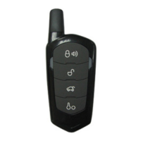
Connector 5 (CN5), 4-Pin (Pre-wired Antenna Cable)
Pin 1 Yellow - RX input. This wire receives the signal from remote.
Pin 2 White - TX output. This wire transmits the signal to remote.
Pin 3 Red – Constant 12V positive (+) output.
Pin 4 Black – Negative (-) ground.