ENGLISH
CONTRACOR
®
Version 3.9
12
4. Set-up, operation and shut-down
4.1. Installation and Set-up
4.1.1 Location
Select a location where compressed air, water and electrical service are available.
Allow for full access to all doors and service areas and for efcient handling of large parts.
4.1.2 Compressed air supply line
Connect compressed air supply line with min. I.D. =1”. to the cabinet inlet. For
connection use a exible hose with same min. I.D. as the main airline. A smaller diameter
air supply line or hose may reduce blasting efciency.
4.1.3 Grounding
Ground the cabinet to prevent static electricity build up. For grounding attach an
external grounded wire to the grounding lug on the cabinet skirt.
ATTENTION!
Be certain that all pipe ttings and hose clamps are tight before using the
blast cabinet. Hose disconnection while under pressure could cause seri-
ous injury.
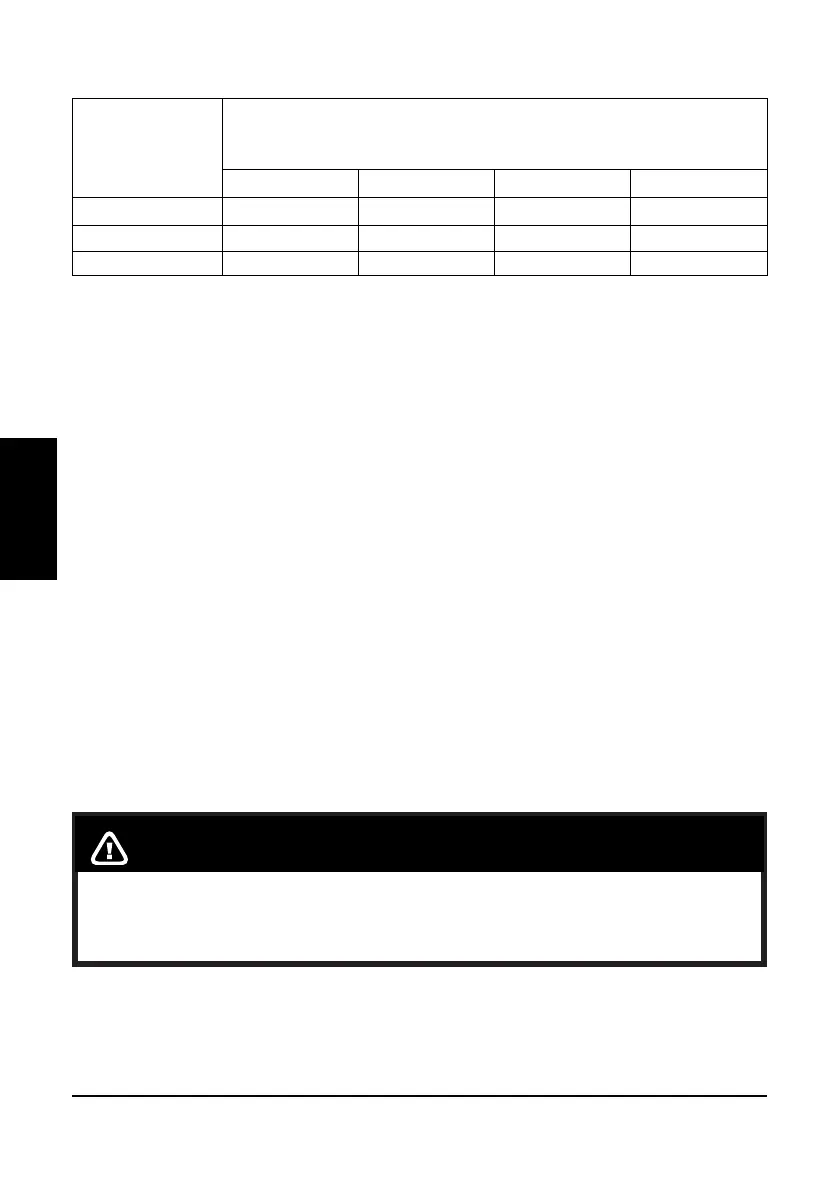
Table 3.2 Air Consumption
Ø
Blast nozzle
(mm)
REQUIRED AIR VOLUME (m³/min.)
at working pressure, bar
3 4 5 6
5,0 0,7 0,8 0,9 1,0
6,5 1,3 1,5 1,7 1,9
8,0 2,0 2,5 2,0 3,3
NOTE: the above table shows only the air required for the blast nozzle. Additional air is
required for the air cartridge cleaning, which must be added to the above values.
The above values are valid for nozzles when new. As nozzle wear increases, so does the
air consumption, up to 70% to 80% more than when new.