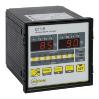
CTT8 instruction manual IM302-U v2.3 pag. 5 / 8
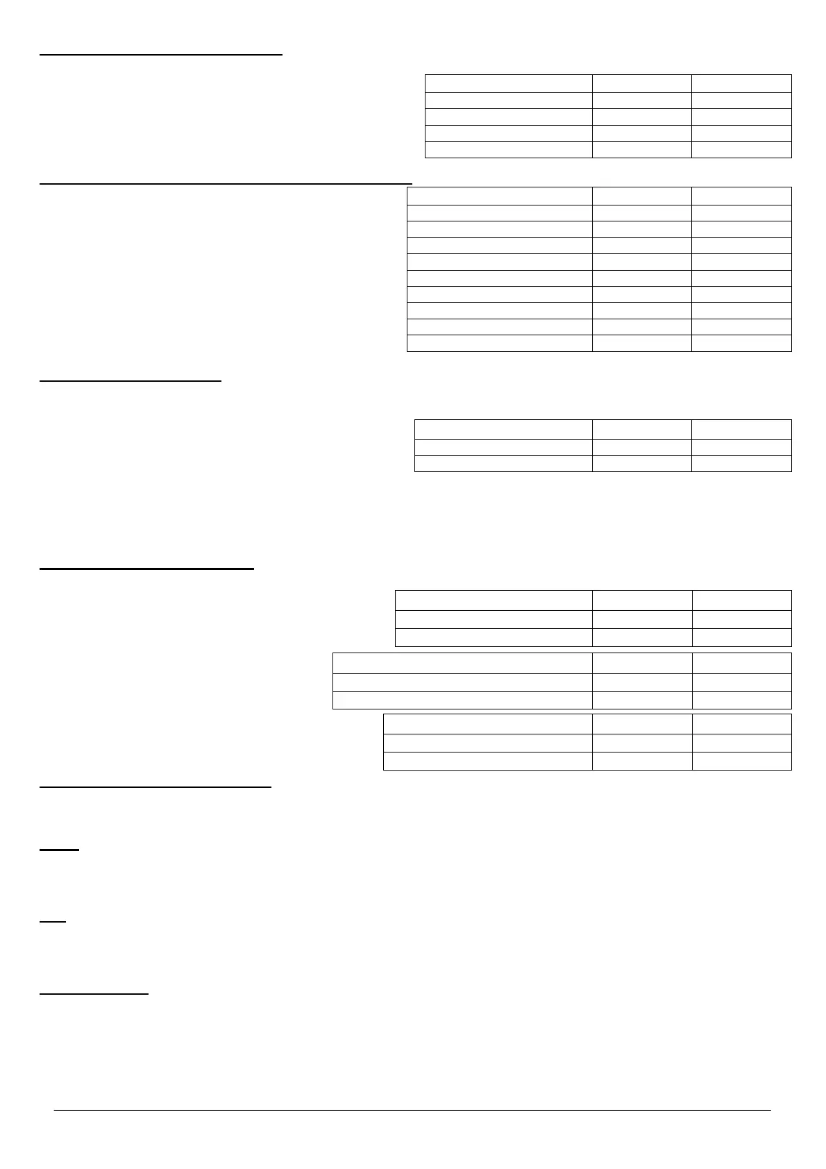
Selection data bit, parity and stop bit
Note: This setting is not significant for the models without the serial interface installed.
This phase is indicated on displays where there is
The type of parity on displays T1-T2-T3-T4;
number of data bit and stop bit on display T5-T6-T7-T8.
With and keys to select the set choice.
Confirm with ENTER.
Selection of the linked channel with the analogue output
Note: This setting is not significant for the models without
the analogue output installed.
This phase is indicated on displays where there is
AN on displays T1-T2-T3-T4,
the measure of the linked channel on displays T5-T6-T7-
T8 (CH 1/2/3/4/5/6/7/8 for measure channel 1 / 2 /
3 / 4 / 5 / 6 / 7 / 8, all to link the output on the measure
channel with the highest temperature).
With and keys to select the set choice.
Confirm with ENTER.
Configuration output signal
Note: This setting is not significant for the models without the analogue output installed.
In this phase it’s possible to define the type of signal of analogue output as 0 ÷ 20 mA or 4 ÷ 20 mA.
This phase is indicated on displays where there is
aN0 -20 to set the output as 0 ÷ 20 mA or
(0 mA = -30° ; 20 mA = 200°)
aN4 -20 to set the output as 4 ÷ 20 mA.
(4 mA = -30° ; 20 mA = 200°)
With and keys to select the options.
Confirm with ENTER.
Note: The maximum load for analogue output is 400 ohm.
Configuration diagnostic probes
This function allows to enable or to disable the control on the probes.
The function control the variation of the temperature in a
defined time. There is a problem if this variation is
higher than a set value.
It’s necessary to set the maximum variation
temperature:
FDC: min 5 °C– max 30 °C
and after the time in which to do the control:
FDC: min 10” – max 90” (period in seconds)
The + key is used to increase the values while the
- key to decrease.
Confirm with ENTER.
The exit of the programming phase
Press the SET key or wait for about 8 seconds without to press any key to come out of the programming phase.
MODALITY OF TRIPPING AND RESTORE
Alarm
At
the overcoming of 1°C of the value of threshold set on the input, after 5 seconds, on the channel where the threshold value
has been exceeded, the ALARM relay is energized and the ALARM led is on. The restore from the alarm condition with relay
de-energized and the relative led off, happen when the temperature go down of 2°C respect at the threshold value set.
Trip
At
the overcoming of 1°C of the value of threshold set on the input, after 5 seconds, on the channel where the threshold value
has been exceeded, the TRIP relay is energized and the TRIP led is on. The restore from the alarm condition with relay de-
energized and the relative led off, happen when the temperature descend of 2°C respect at the threshold value set.
To silence alarm
If the Hold function is disabled it’s possible to silence the alarm condition that there is on the measure input.
When there is an alarm condition the ALARM relay and the “ALARM” optical signalling are enabled.
Pressing the Reset button the relay is de-energized while the optical signalling of the alarm condition become flash.
If the temperature increase up to reach the TRIP temperature minus 1°C, the relay and the optical signalling are enabled
another time. If after the reset, the temperature go down under the threshold value set, the flashing optical signalling will
be automatically deleted.
Set T1-T2-T3-T4 T5-T6-T7-T8
No parity / 8 data bit – 1stop bit
NO 8-1
No parity / 8 data bit – 2stop bit
NO 8-2
Odd parity / 8 data bit – 1stop bit
ODD 8-1
Even parity / 8 data bit – 1stop bit
EVE 8-1
Linked channel T1-T2-T3-T4 T5-T6-T7-T8
Channel with the highest temperature
AN all
Measure channel CH 1
AN ch1
Measure channel CH 2
AN ch2
Measure channel CH 3
AN ch3
Measure channel CH 4
AN Ch4
Measure channel CH 5
AN Ch5
Measure channel CH 6
AN Ch6
Measure channel CH 7
AN Ch7
Measure channel CH 8
AN Ch8
Signal configuration T1-T2-T3-T4 T5-T6-T7-T8
Output proportionally 0 – 20 mA
AN 0 -20
Output proportionally 4 – 20 mA
AN 4 -20
Setting FDC modality
T1-T2-T3-T4 T5-T6-T7-T8
FDC mode disabled
FDC Off
FDC mode enabled
FDC ON
Temperature configuration FDC
T1-T2-T3-T4 T5-T6-T7-T8
Min °C
FDC
5°
Max ° C
FDC
30°
Period configuration FDC
T1-T2-T3-T4 T5-T6-T7-T8
Min in seconds
FDC 10’’
Max in seconds
FDC 90’’
 Loading...