Do you have a question about the Contrel EMS-96 and is the answer not in the manual?
Details the different models and their communication/I/O configurations.
Lists available software options and their enablement requirements.
Provides a comprehensive list of all measurable parameters and their availability.
Provides essential warnings for users before installing and using the instrument.
Outlines safety standards and precautions for safe operation and maintenance.
Describes the instrument's power supply options and operation.
Details the terminals and specifications for voltage input connections.
Explains current input connections, transformer requirements, and ranges.
Describes the technical features of the available digital outputs.
Details the technical features of optional digital input modules.
Outlines the technical features of optional analog output modules.
Details the configuration for 4 digital inputs and 4 pulse/state digital outputs.
Describes the configuration for 8 digital outputs, including pulse/state types.
Details the configuration for 2 analog outputs and 2 pulse/state digital outputs.
Describes the configuration for 2 analog outputs and 4 pulse/state digital outputs.
Details the configuration for 4 analog outputs and 2 pulse/state digital outputs.
Describes the configuration for 4 analog outputs and 4 pulse/state digital outputs.
Explains the RS485 serial port options for Modbus communication and software updates.
Details the Profibus-DP interface, its pin-out, and baud rate detection.
Describes the Ethernet port features, LEDs, and available options for network communication.
Explains the MBUS communication wiring and its purpose.
Details the functionality of directional, Enter, and Esc keys for navigation and control.
Explains the meaning and function of the LEDs on the instrument's front panel.
Guides through the essential parameters to set during the first instrument setup.
Visualizes the structure of the Measures menu, showing available parameter groups.
Illustrates the hierarchical structure of the Setup menu for configuration.
Details the 'General' section within the Setup menu.
Details the 'Measure' section within the Setup menu.
Details the 'User pages' section within the Setup menu.
Details the 'Communication' section within the Setup menu.
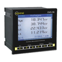
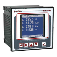
Displays real-time electrical parameters such as voltage, current, and power.
Shows relative, absolute minimum, and maximum values for measured parameters.
Presents average values and peak demand for electrical parameters.
Displays energy consumption data organized by timebands.
Details how to read data from connected slave devices.
Configuration of password, reset, date/time, utility, display, and graphics.
Configuration of transform ratio, time window, frequency, SAG, and wiring.
Setup for user page type, composition, titles, and key texts.
Setup for COM ports, Profibus, Ethernet, and Mbus interfaces.
Configuration of digital and analog inputs/outputs.
Configuration of setpoints for alarms and actions.
Configuration of data logging parameters.
Configuration for access keys, password protection, and various reset options.
Settings for the instrument's internal clock and date/time synchronization.
Settings for language, theme, text size, LED behavior, and display brightness.
Configuration options related to graphical trend displays.
Configures CT and VT ratios for accurate electrical measurements.
Sets time windows for averaging and frequency base for SAG detection.
Configures threshold and time for detecting voltage sags.
Sets wiring types, neutral current measurement, and power factor conventions.
Selects how timebands are managed: manual, DI, or preset.
Defines daily schedules for timeband changes.
Sets longer-term plans for timeband transitions across months and days.
Chooses the type of data (instant, averages, energies, setpoint) displayed on user pages.
Selects up to six measures to display in each row of a user page.
Configures COM ports, slave addresses, types, names, and communication parameters.
Sets up the Profibus-DP interface, including node address.
Configures Ethernet (IP, gateway) and M-Bus (address, baud rate) interfaces.
Defines which M-Bus data groups and measures are read.
Sets up digital outputs for pulse/state modes and associates them with measures.
Configures digital inputs for counting or triggering, with multiplier/divider settings.
Configures analog outputs for voltage or current, including measure association and thresholds.
Detailed settings for setpoints: source, limits, debounces, logic operations, operands, and actions.
Configures generic data logging, sampling, storage, and selected measures.
Sets up smart logging for average, min, and max values over a defined analysis window.
Configures trigger logging based on specific events like digital input changes or setpoints.
Configures timed data logging based on specific intervals and days of the week.
Defines mathematical operations on measures, including operands, multipliers, and divisors.
Lists the categories for measurement acronyms.
Explains acronyms for instantaneous measurements.
Explains acronyms for average measurements.
Explains acronyms for energy and timeband data.
Details auxiliary power, energy precision, frequency, power factor, and measurement ranges.
Covers voltage/current inputs, installation types, and overload capabilities.
Provides physical dimensions, weight, and operating temperature ranges.
Specifies RS485 communication protocol and features.
| Brand | Contrel |
|---|---|
| Model | EMS-96 |
| Category | Measuring Instruments |
| Language | English |