EMS-96 Instruction Manual IM1200-U v1.6 Pag. 26 / 48
Measure
Setup Measure Transform ratio
It’s the ratio between the primary and the secondary circuit of the external current transformers.
4
th
current input transform ratio.
It’s the ratio between the primary and the secondary circuit of the voltage transformers.
Setup Measure Time window
1 / 2 / 3 / 5 / 6 / 10 / 12 / 15 / 20 / 30 / 60
The time used to calculate the average, maximum, minimum values and the expected power.
The type of the window to calculate the average values and expected power.
Setup Measure Frequency
Select the base frequency of the inputs (voltages and currents).
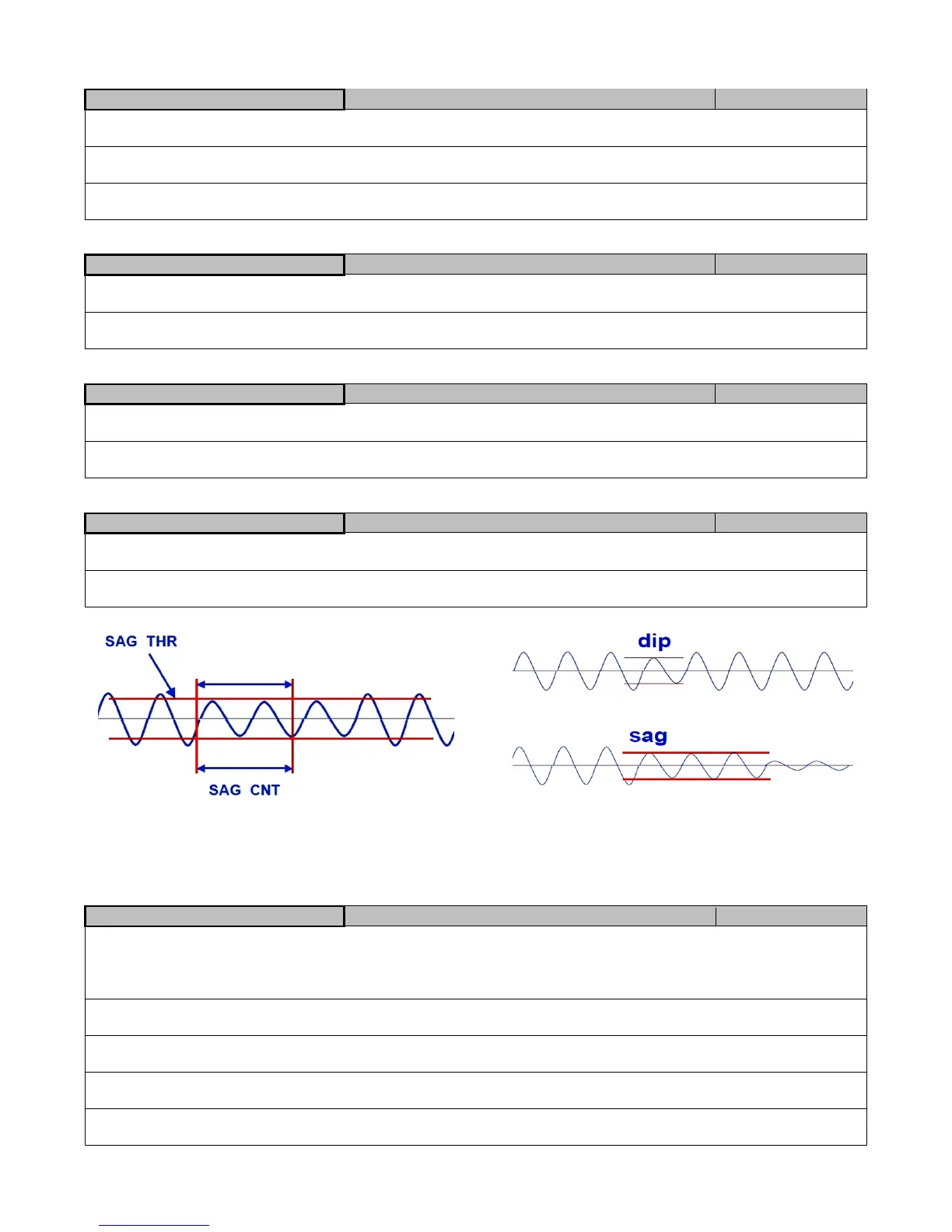
It’s the phase that will be monitored to detect of SAG and to read the actual frequency.
If the voltage value drops below the setting, the software considers the event as SAG.
If the voltage value drops below for a time greater than the setting, the software considers the event as SAG.
Fig.1: Sag parameters Fig.2: Sag Explanation
A sag is defined as an under voltage condition that persists for more than one period of base frequency. A shorter under voltage
condition is called a dip (see Fig. 2). The occurrence of sag could announce an impending loss of power.
To set the sag register the voltage must be under the Threshold value for a minimum time defined in Time.
Setup Measure Wiring/Conventions
3 phase [4 or 3 wires] / ARON / balanced 3-phase / 3-ph
multiload balanced / single-phase / 1-phase multiload /
multi single-phase / 2-phase 3 wires
On this item appears Measured if the CT is present or Computed if the CT is not present. The user can change the set showed.
See the following picture for details on the selected configuration.
It allows to modify the basic unit of measure of the powers (showed and read by the communication interface).
It allows to modify the basic unit of measure of the energies (showed and read by the communication interface).