Do you have a question about the Contrel CTT4 and is the answer not in the manual?
Device CTT4 controls and visualizes temperatures from RTD PT100 probes.
Lists available accessories and optional features for the device.
Instructions for safe and proper installation of the device.
Critical safety precautions for installation and device usage.
Guidance on correctly wiring RTD Pt100 thermometer sensors.
Diagram and explanation for connecting probes and auxiliary power.
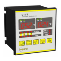
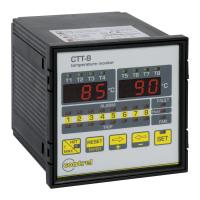
Explains the meaning of LEDs, displays, and buttons on the front panel.
How to enable/disable the Hold function for alarm rearming.
Setting whether 3 or 4 inputs are active for measurement.
Configuration options for the device's ventilation control function.
Setting temperature thresholds for ventilation switch-on and switch-off.
Setting the temperature value to disable ventilation.
Setting the temperature value to enable ventilation.
Configuring alarm and trip temperature thresholds for measurement channels.
Setting the communication speed for the serial port.
Configuring data bits, parity, and stop bits for serial communication.
Linking the analog output signal to a specific temperature channel.
Setting the analog output signal type: 0-20mA or 4-20mA.
Enabling/disabling probe variation control and setting related parameters.
Procedure for silencing an alarm when the Hold function is disabled.
Explains probe diagnostics and fault signaling mechanisms.
Summarizes the status of device relays in different operational modes.
How to view and reset the maximum recorded temperature values.
Displays channels with the highest temperatures among pairs.
Procedure to test all indicator lights on the device.
How to view current measured temperatures on the device display.
Method to disable unused probe inputs by connecting a resistor.
Provides physical dimensions and mounting information for the device.
The CTT4 is a temperature monitor device designed for controlling electric machines, transformers, and motors. It monitors temperature levels and signals critical conditions or disables the controlled machine. For instance, it can monitor the temperatures of three-phase coils and the nucleus of a transformer, using a tripped output (TRIP) to cut off the load and control ventilation functions.
The device provides two alarm levels (alarm-tripped) for each measurement channel, activating corresponding output relays for remote signaling or machine shutdown. The front panel features a double 3-digit display for visualizing temperatures and alarm statuses, along with five buttons for programming. It also includes functions for ventilation control, storing maximum values, and recording tripped events.
A key feature is the RS485 serial communication port, enabling connection to acquisition systems (PC, PLC, SCADA, etc.) for data measurement, control, and device programming. The MODBUS-RTU protocol is used for communication, detailed in a separate manual. A Windows-based software is available for comprehensive device management, including control, data storage, alarm recording, and more. An analog output, settable to 0-20mA or 4-20mA with a 200°C end-scale, can be linked to one of the channels or the highest of the four temperature channels.
The CTT4 uses RTD Pt100 probes for temperature measurement. Each channel has two alarm levels: ALARM and TRIP. The ALARM and TRIP relays activate when their respective thresholds are exceeded. The FAULT relay is normally energized and de-energizes in the presence of an anomaly with the Pt100 probe or the device itself. The FAN relay controls a cooler's fan based on set switch-on and switch-off thresholds.
Upon power-on, the device displays internal software index, then measured temperatures. Pressing SET for a few seconds enters programming mode. Settings are displayed sequentially. To exit without saving, press SET without confirming with ENTER. To modify values, use the ⇐- and ⇒+ keys, then ENTER to store. ENTER also moves to the next function.
HOLD Function: This is the first programming function. When enabled, alarms can only be manually reset with the RESET button when the temperature is below the threshold. If disabled, alarms can be reset even if the temperature is above the threshold, but will automatically clear once the temperature drops below the threshold.
Number of Active Inputs: Selects between 3 or 4 active inputs. If 3 inputs are chosen, the T4 display remains off.
Ventilation Control: After input selection, the FAN LED illuminates. Settings include inhibited ventilation control or active control on 3 or 4 inputs (or only on the fourth input for 4-input mode). Thresholds for enabling and disabling ventilation are programmable.
Alarm and Tripped Thresholds: Programming starts with channel 1. The ALARM LED indicates alarm threshold programming, and the TRIP LED indicates tripping threshold programming. Values are set using ⇐- and ⇒+ keys within specified temperature ranges. This process is repeated for all measure channels.
This function enables/disables control on probes and monitors temperature variation over time. If the variation exceeds a set value, it indicates a problem.
Exit Programming: Press SET or wait 8 seconds without pressing any key.
The device includes diagnostic functions for thermic probes:
The manual provides a table detailing the contact status (CLOSED/OPEN) for ALARM, TRIP, FAN, and FAULT relays in DISABLE, ENABLE, and UNPOWERED states.
Pressing T.MAX displays the maximum measured temperature (flashing). Use ⇐- and ⇒+ keys to navigate between T1-T3 and T2-T4. After 8 seconds of inactivity, the device returns to current temperature display. To reset maximum values, press T.MAX and ⇐- simultaneously.
Press HOT for a few seconds to activate the HOT LED. The left display shows the hotter temperature between inputs 1 and 2, and the right display shows the hotter temperature between inputs 3 and 4. Press HOT again to return to standard display.
Press ⇐- and ⇒+ keys simultaneously to make all LEDs flash for a few seconds.
The left display shows T1 and T2 temperatures (0°C to +220°C). The right display shows T3 and T4 temperatures (0°C to +220°C). Use ⇐- and ⇒+ keys to change displayed channels.
If an input is not used, a resistance of 100-120 ohms, 0.25W must be connected across terminals 1-2 (for Ch1), 4-5 (for Ch2), 7-8 (for Ch3), or 10-11 (for Ch4).
Follow the wiring diagram. Do not invert red and white insulated conductors. For 3-wire Pt100 probes, the third wire compensates for conductor resistance. For 2-wire probes (normally white and red), short-circuit terminals 1-2, 4-5, 7-8, or 10-11 with the red wires. To reduce external noise:
| Brand | Contrel |
|---|---|
| Model | CTT4 |
| Category | Measuring Instruments |
| Language | English |