CTT4 instruction manual IM301-U v2.1 pag. 7 / 8
TECHNICAL FEATURES
auxiliary power supply 20÷250Vca/cc ±15% or 115-230-400 Vca 50-60Hz
maximum consumption 4 VA
measure inputs 3 - 4 inputs by RTD Pt100
interval of measure 0 °C ÷ +220 °C / precision ± 2 °C
tripped delay - hysteresis 5 seconds – 2 °C
measure visualization 2 displays with led 7 segments, 3 digit
outputs 4 relay NO-C-NC, 8 A resistive load
output functions alarm, trip, fan, auto-diagnostic
functions programmable ALARM, TRIP, HOLD, FAN, T.MAX, HOT
connection extractible terminal with screws, section wires max 2,5 mm
2
insulation
2500 Vrms 50 hz per 60 sec :U aux - input Pt100 /
U aux - relay outputs / inputs Pt100 - relay outputs
protection degree IP52 front panel (IP65 with optional protection cover), IP20 rear panel, as CEI-EN 60529
dimensions – enclosure
flash mounting DIN 96x96mm, depth 120mm /
Enclosure thermoplastic self-extinguishing as UL94 V0
working temperature -10 ÷ 55°C, humidity max 90%
storing temperature -25 ÷ +80°C
standards
electromagnetic compatibility CEI-EN 50081-2 CEI-EN50082-2
security CEI 41.1, CEI-EN 60255-
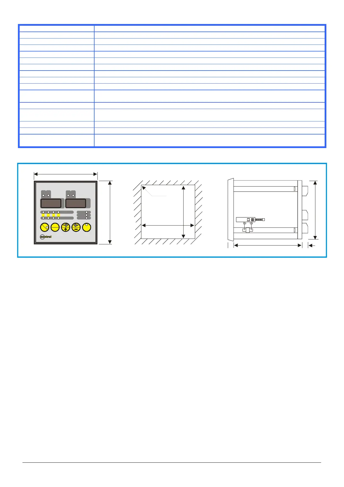
DIMENSIONS
149
90
106
92
92
R3
96
96
°C
T3 T4
1
234
ALARM FAULT
HOLD
FAN
SET
TRIP
T1 T2
temperature monitor devic e
TMD-4
HOT
T.
MAX
RESET
ENTER
°C °C
T3
T4
1
2
34
ALARM
FAULT
HOLD
FAN
SET
TRIP
T1
T2
temperature monitor device
CTT4
HOT
T.
MAX
RESET
ENTER
°C
Contact the technical assistance or refer at specific document for application don’t described in this manual.
NOTE
At reason of the evolution of standards and products, the company reserves to modify in every time the features of the product
described in this document, that it’s necessary to verify preventively.
The liability of the producer for damage caused by defect of the product ”can be reduced or deleted (…) when the damage is caused
joint by a defect of product or for blame of the damaged or a person of which the damaged is responsible” (Article 8, 85/374/CEE).