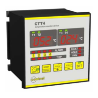
CTT4 instruction manual IM301-U v2.1 pag. 6 / 8
MODALITY OF TRIPPING AND RESTORE
Alarm
At the overcoming of 1°C of the value of threshold set on the input, after 5 seconds, on the channel where the threshold
value has been exceeded, the ALARM relay is energized and the ALARM led is on. The restore from the alarm condition
with relay de-energized and the relative led off, happen when the temperature go down of 2°C respect at the threshold
value set.
Trip
At the overcoming of 1°C of the value of threshold set on the input, after 5 seconds, on the channel where the threshold
value has been exceeded, the TRIP relay is energized and the TRIP led is on. The restore from the alarm condition with
relay de-energized and the relative led off, happen when the temperature descend of 2°C respect at the threshold value
set.
To silence alarm
If the Hold function is disabled it’s possible to silence the alarm condition that there is on the measure input. When there
is an alarm condition the ALARM relay and the “ALARM” optical signalling are enabled. Pressing the Reset button the
relay is de-energized while the optical signalling of the alarm condition become flash. If the temperature increase up to
reach the TRIP temperature minus 1°C, the relay and the optical signalling are enabled another time. If after the reset,
the temperature go down under the threshold value set, the flashing optical signalling will be automatically deleted.
DIAGNOSTIC
The device is provided of the thermic probes diagnostic function.
The condition controlled on the measure input are:
Probe Pt100 interrupted: signalling on the display of the message O P E (open).
Probe in short circuit: signalling on the display of the message S H r (short circuit).
Probe out of order for temperature reading wrong: signalling on the display of the message F DC.
When the device switch on the auto-diagnostic FAULT relay commute and it remain in the status of energized until one of
the conditions above described appears, for a failure of the device or if the power supply is absent.
The anomaly condition is signalled also by the FAULT led on.
Every time that a probe of a channel is out of order because it’s interrupted (OP E) or in short circuit (SHR) or the delta of
temperature is too much elevated (F DC), the led of the corresponding channel flash until stopping of the anomaly. The
alarm of interrupted probe (SHR) or open probe (OP E) will be reset automatically while the alarm for the delta of
temperature (F DC) disappears only pressing the ENTER key, and to keep it pressed, to press the
⇒+ key at least 5
seconds.
The status of the contact of the relay (all available with exchange contact) is showed in the following table:
RELAY DISABLE STATUS ENABLE STATUS UNPOWERED STATUS
ALARM ALARM OFF: CLOSED 29-30 ALARM ON: CLOSED 29-31 CLOSED 29-30
TRIP TRIP OFF: CLOSED 32-33 TRIP ON: CLOSED 32-34 CLOSED 32-33
FAN FAN OFF: CLOSED 35-36 FAN ON: CLOSED 35-37 CLOSED 35-36
FAULT FAULT OFF: CLOSED 38-40 FAULT ON: CLOSED 38-39 CLOSED 38-39
VISUALIZATION OF THE MAXIMUM MEASURED VALUE OF TEMPERATURE
Pressing the Tmax key on displays appear, in modality flashing, the maximum measured value of temperature. To pass
from the visualization of the maximum temperature T1-T3 to T2-T4 to use ⇐ and ⇒ keys. After an interval of about 8
seconds without to press any key the device come back to display the value of measured temperature.
To reset the value of the maximum temperature it’s necessary to go in the visualization maximum values and after to
press at the same time Tmax and ⇐.
VISUALIZATION OF THE CHANNELS WITH THE HIGHER TEMPERATURE
Press the HOT key for same second up to switch on the HOT led.
On the left display of the front panel will appear the temperature of the measure channel hotter between the inputs 1 and
2.
On the right display on the front panel will appear the temperature of the measure channel hotter between the inputs 3 and
4.
To come back in the standard modality of measure visualization press the HOT key for some second up to switch off the
relative led of signalling.
TEST OF THE LIGHT SIGNALLING
Press at the same time
⇐ and ⇒ keys: all of the light signalling will start to flash for some seconds.
VISUALIZATION OF THE MEASURED TEMPERATURE
On the display on the left of the front panel appears the temperature of the channels T1 T2 in the range 0°C ÷ +220°C.
On the display on the right on the front panel appears the temperature of the channel T3 T4 in the range 0°C ÷
+220°C.
Use ⇐ and ⇒ keys to change the measure channels displayed.
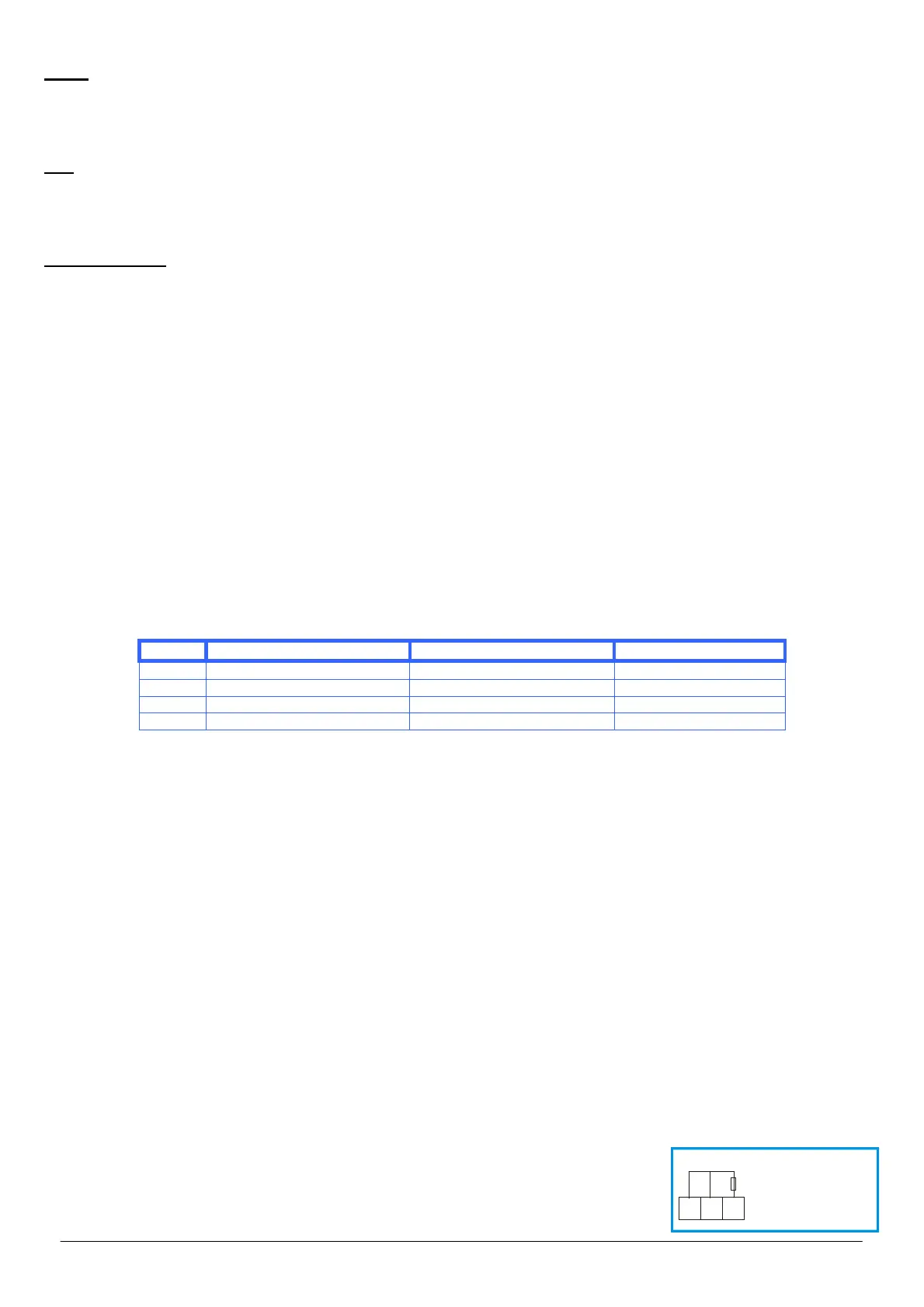
EXCLUSION OF THE PROBE INPUTS NOT USED
If one or more inputs are not used, it’s need to connect a resistance of value included
between 100 and 120 ohm, 0.25W.
In the figure is showed the connection to disable the input Ch1. The same connection
can be used also for the other inputs.
Ch1
1
2
3
R = 100 ÷ 120 ohm
0,25W
 Loading...