CTT4 instruction manual IM301-U v2.1 pag. 2 / 8
OUTPUT RELAYS
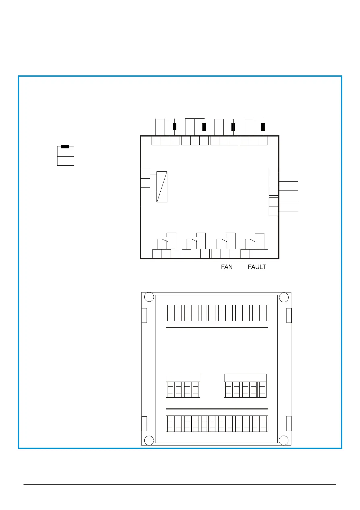
For the connection of the output contacts of relays it’s necessary to follow the indication in the diagram.
The ALARM and TRIP relays commute when the threshold set are to get over.
The FAULT relay is normally energized and it commute in presence of an anomaly on the Pt100 or on device. During the
normally functioning of the device the contact 38-39 will be open while the 39-40 will be closed.
The FAN relay is used to control the fun of cooler, in function of the threshold set of switch on and switch off.
WIRING CONNECTION
7586914 10211312
25 2826 27
44 45
41 42 43
29 30 31 32 33 34
35 36 37 38 39 40
1
Input thermometric probes Pt 100
Ch2
Ch3
Ch4
725869
1
Ch1
410211312
TRIP
LARM
29 30 31 32 33 34 35 36 37 38 39 40
41
42
43
44
45
25
26
27
28
Serial
output
Rs485
(option)
Relay outputs
B
gnd
*
CTT4
Auxiliary power supply
U aux:
25 - 27: 24 ÷ 230V ca/cc
or
25 - 26: 115 Vca
25 - 27: 230 Vca
25 - 28: 400 Vca
*
white
red
red
Pt 100
view rear panel
of the instrument with terminals
for the connections
Analog
output
0-20mA
(4-20mA)
(option)
O+
O-
U aux.
*