Control4 CORE Lite Controller
Installation Guide
Supported model
• C4-CORE-LITE CONTROL4 SINGLE ROOM HUB & CONTROLLER
Introduction
Designed for an exceptional family room entertainment experience, the Control4®
CORE Lite Controller does more than automate the gear around your TV; it is the ideal
smart home starter system with entertainment built in.
The CORE Lite delivers a beautiful, intuitive, and responsive on-screen user interface
with the ability to create and enhance the entertainment experience for any TV in the
house. The CORE Lite can orchestrate a wide range of entertainment devices including
Blu-ray players, satellite or cable boxes, game consoles, TVs, and virtually any product
with infrared (IR) or serial (RS-232) control. It also features IP control for Apple TV, Roku,
televisions, AVRs, or other network-connected devices, as well as secure wireless Zigbee
control for lights, thermostats, smart locks, and more.
For entertainment, the CORE Lite also includes a built-in music server that allows you to
listen to your own music library, stream from a variety of leading music services, or from
your AirPlay-enabled devices using Control4 ShairBridge technology.
Box contents
The following items are included in the CORE Lite controller box:
• CORE Lite controller
• AC power cord
• IR emitters (2)
• Rubber feet (2, pre-installed)
Accessories available for purchase
• CORE 1 Wall-Mount Bracket (C4-CORE1-WM)
• Control4 1U Rack-Mount Kit, Single/Dual Controller (C4-CORE1-RMK)
• Control4 Dual-Band Wi-Fi USB Adapter (C4-USBWIFI OR C4-USBWIFI-1)
• Control4 3.5 mm to DB9 Serial Cable (C4-CBL3.5-DB9B)
Requirements and specifications
Note: We recommend using Ethernet instead of Wi-Fi for the best network
connectivity.
Note: The Ethernet or Wi-Fi network should be installed before starting the
CORE Lite controller installation.
Note: The CORE Lite requires OS 3.3.3 or newer.
Composer Pro software is required to configure this device. See the Composer Pro User
Guide (ctrl4.co/cpro-ug) for details.
Warnings
Caution! To reduce the risk of electrical shock, do not expose this apparatus to
rain or moisture.
AVERTISSEMENT ! Pour réduire le risque de choc électrique, n’exposez pas cet
appareil à la pluie ou à l’humidité.
Caution! In an over-current condition on USB, the software disables the
output. If the attached USB device does not appear to power on, remove the
USB device from the controller.
AVERTISSEMENT ! Dans une condition de surintensité sur USB ou sortie de
contact le logiciel désactive sortie. Si le périphérique USB ou le capteur
de contact connecté ne semble pas s’allumer, retirez le périphérique du
contrôleur.
Specifications
Inputs / Outputs
Video out
1 video out—1 HDMI
Video
HDMI 2.0a; 1920×1080 @ 60Hz; HDCP 2.2 and HDCP 1.4
Audio out
1 audio out—HDMI
Audio playback formats
AAC, AIFF, ALAC, FLAC, M4A, MP2, MP3, MP4/M4A, Ogg
Vorbis, PCM, WAV, WMA
High-resolution audio playback
Up to 192 kHz / 24 bit
Network
Ethernet
1 10/100/1000BaseT compatible network port
Wi-Fi
Optional Dual-Band Wi-Fi USB Adapter
(2.4 GHz, 5 Ghz, 802.11ac/b/g/n/a)
Zigbee Pro
802.15.4
Zigbee antenna
Internal antenna
USB port
1 USB 2.0 port—500mA
Control
IR out
3 IR out—5V 27mA max output
IR capture
1 IR receiver—front, 20-60 KHz
Serial out
1 serial out (shared with IR out 1)
Power
Power requirements
100-240 VAC, 60/50Hz
Power consumption
Max: 18W, 61 BTUs/hour
Idle: 12W, 41 BTUs/hour
Other
Operating temperature
32˚F ~ 104˚F (0˚C ~ 40˚C)
Storage temperature
4˚F ~ 158˚F (-20˚C ~ 70˚C)
Dimensions (H × W × D)
1.22 × 7.75 × 4.92" (31 × 197 × 125 mm)
Weight
1.15 lb (0.68 kg)
Additional resources
The following resources are available for more support.
• Control4 CORE series help and information: ctrl4.co/core
• Snap One Tech Community and Knowledgebase: tech.control4.com
• Control4 Technical Support: ctrl4.co/techsupport
• Control4 website: www.control4.com
Connecting the IR ports/serial ports (optional)
The controller provides three IR ports, and port 1 can be reconfigured independently
for serial communication. If not used for serial, they can be used for IR. Connect a serial
device to the controller using the Control4 3.5 mm-to-DB9 Serial Cable (C4-CBL3.5-
DB9B, sold separately).
1 The serial ports support baud rates between 1200 to 115200 baud for odd and even
parity. The serial ports do not support hardware flow control.
2 See Knowledgebase article #268 (ctrl4.co/contr-serial-pinout) for pinout diagrams.
3 To configure a port for serial or IR, make the appropriate connections in your project
using Composer Pro. See the Composer Pro User Guide for details.
Note: The serial ports can be configured as straight-through or null with
Composer Pro. Serial ports by default are configured straight-through and can
be changed in Composer by selecting Null Modem Enabled (SERIAL 1).
Setting up IR emitters
Your system may contain third-party products that are controlled through IR commands.
1 Connect one of the included IR emitters to an IR OUT port on the controller.
2 Place the stick-on emitter end onto the IR receiver on the Blu-ray player, TV, or other
target device to emit IR signals from the controller to the target device.
Setting up external storage devices (optional)
You can store and access media from an external storage device, for example, a network
hard drive or USB memory device, by connecting the USB drive to the USB port and
configuring or scanning the media in Composer Pro.
Note: We support only externally powered USB drives or solid state USB sticks.
Self-powered USB drives are not supported.
Note: When using USB storage devices on an CORE Lite controller, you can use
only one partition with a 2 TB maximum size. This limitation also applies to the
USB storage on other controllers.
Composer Pro driver information
Use Auto Discovery and SDDP to add the driver to the Composer project. See the
Composer Pro User Guide (ctrl4.co/cpro-ug) for details.
OvrC setup and configuration
OvrC gives you remote device management, real-time notifications, and intuitive
customer management, right from your computer or mobile device. Setup is
plug-and-play, with no port forwarding or DDNS address required.
To add this device to your OvrC account:
1 Connect CORE Lite controller to the Internet.
2 Navigate to OvrC (www.ovrc.com) and log in to your account.
3 Add the device (MAC address and Service Tag numbers needed for authentication).
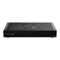
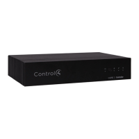
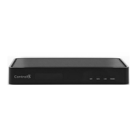
Front view
A Activity LED—The Activity LED shows when the controller is streaming audio.
B IR window—IR receiver for learning IR codes.
C Caution LED—This LED shows solid red, then blinks blue during the boot process.
Note: The Caution LED blinks orange during the factory restore process. See
“Reset to factory settings” in this document.
D Link LED—The LED indicates that the controller has been identified in a Control4
project and is communicating with Director.
E Power LED—The blue LED indicates that AC power is present. The controller turns on
immediately after power is applied to it.
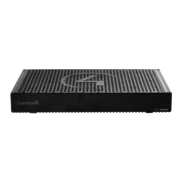
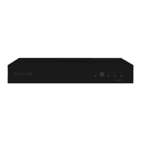
Back view
A Power port—AC power connector for an IEC 60320-C5 power cord.
B IR OUT/SERIAL—3.5 mm jacks for up to three IR emitters or for a combination of IR
emitters and serial devices. Port 1 can be configured independently for serial control
(for controlling receivers or disc changers) or for IR control. See “Connecting the IR
ports/serial ports” in this document for more information.
C USB—One port for an external USB drive (such as a USB stick formatted FAT32). See
“Setting up external storage devices” in this document.
D HDMI OUT—An HDMI port to display navigation menus. Also an audio out over HDMI.
E ID button and RESET—ID button is pressed to identify the device in Composer Pro.
The ID button on the CORE Lite is also an LED that displays feedback useful during a
factory restore. The RESET pinhole is used to reset or factory restore the controller.
F ETHERNET—RJ-45 jack for a 10/100/1000BaseT Ethernet connection.
Installation instructions
To install the controller:
1 Ensure that the home network is in place before starting system setup. An Ethernet
connection to the local network is required for setup. The controller requires a
network connection to use all of the features as designed. After initial configuration,
Ethernet (recommended) or Wi-Fi (with an optional adapter) can be used to
connect the controller to web-based media databases, communicate with other IP
devices in the home, and access Control4 system updates.
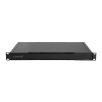
2 Mount the controller near the local devices you need to control. The controller
can be hidden behind a TV, mounted on a wall, installed in a rack, or placed on a
shelf. The CORE 1/Lite Rack Mount Kit is sold separately and is designed for easy
installation of up to two CORE 1/Lite controllers side by side in a rack. The CORE 1/
Lite Wall-Mount Bracket is sold separately and designed for easy installation of the
CORE Lite controller behind a TV or on the wall.
3 Connect the controller to the network.
• Ethernet—To connect using an Ethernet connection, connect the network cable
into the controller’s RJ-45 port (labeled ETHERNET) and into the network port on
the wall or at the network switch.
• Wi-Fi—To connect using Wi-Fi, first connect the unit to Ethernet, connect the
Wi-Fi adapter to the USB port, and then use Composer Pro System Manager to
reconfigure the unit for Wi-Fi.
4 Connect system devices. Attach IR and serial devices as described in “Connecting
the IR ports/serial ports” and “Setting up IR emitters.”
5 Set up any external storage devices as described in “Setting up external storage
devices” in this document.
6 Connect the power cord to the controller’s power port and then into an electrical
outlet.
A
CB
D
E
E
A B C D F