EasyManua.ls Logo

Control 4 CORE-5 - User Manual

Control 4 CORE-5
11 pages
Print Icon
To Next Page IconTo Next Page
Loading...
Front view
A Activity LEDThe LED indicates that the controller is streaming audio.
B IR window—IR receiver for learning IR codes.
C Caution LEDThis LED shows solid red, then blinks blue during the boot
process.
Note: The Caution LED flashes orange during the factory restore
process. See “Reset to factory settings” in this document.
D Link LEDThe LED indicates that the controller has been identified in a
Control4 Composer project and is communicating with Director.
E Power LEDThe blue LED indicates that AC power is connected. The
controller turns on immediately after power is applied to it.
Back view
A Power plug port—AC power receptacle for an IEC 60320-C13 power cord.
B Contact/Relay port—Connect up to four relay devices and four contact
sensor devices to the terminal block connector. Relay connections are
COM, NC (normally closed), and NO (normally open). Contact sensor
connections are +12, SIG (signal), and GND (ground).
C ETHERNETRJ-45 jack for a 10/100/1000 BaseT Ethernet connection.
D USBTwo port for an external USB drive or the optional Dual-Band WiFi
USB Adapter. See “Set up external storage devices” in this document.
E HDMI OUTAn HDMI port to display system menus. Also an audio out over
HDMI.
F ID and FACTORY RESETID button to identify the device in Composer Pro.
The ID button on the CORE-5 is also an LED that displays feedback useful
during a factory restore.
G ZWAVE—Antenna connector for the Z-Wave radio
H SERIAL—Two serial ports for RS-232 control. See “Connecting the serial
ports” in this document.
I IR / SERIAL—Eight 3.5 mm jacks for up to eight IR emitters or for a
combination of IR emitters and serial devices. Ports 1 and 2 can be
configured independently for serial control or for IR control. See “Setting up
IR emitters” in this document for more information.
J DIGITAL AUDIO—One digital coax audio input and three output ports.
Allows audio to be shared (IN 1) over the local network to other Control4
devices. Outputs audio (OUT 1/2/3) shared from other Control4 devices or
from digital audio sources (local media or digital streaming services such
as TuneIn.)
K ANALOG AUDIO—One stereo audio input and three output ports. Allows
audio to be shared (IN 1) over the local network to other Control4 devices.
Outputs audio (OUT 1/2/3) shared from other Control4 devices or from
digital audio sources (local media or digital streaming services such as
TuneIn.)
L ZIGBEE—Antenna for the Zigbee radio.
Installing the controller
To install the controller:
1 Ensure that the home network is in place before starting system setup.
The controller requires a network connection, Ethernet (recommended)
or WiFi (with optional adapter), to use all of the features as designed.
When connected, the controller can access web-based media databases,
communicate with other IP devices in the home, and access Control4
system updates.
2 Mount the controller in a rack or stacked on a shelf. Always allow plenty
of ventilation. See “Mounting the controller in a rack” in this document.
A B C D
E
A B C D E F H I J
K
LG
Control4 CORE-5 Controller
Installation Guide
Supported model
C4-CORE5 Control4 CORE-5 Hub & Controller
Box contents
The following items are included in the box:
CORE-5 controller
AC power cord
IR emitters (8)
Rack ears (2, pre-installed on the CORE-5)
Rubber feet (2, in box)
External antennas (2)
Terminal blocks for contacts and relays
Accessories sold separately
Control4 3-Meter Wireless Antenna Kit (C4-AK-3M)
Control4 Dual-Band WiFi USB Adapter (C4-USBWIFI OR C4-USBWIFI-1)
Control4 3.5 mm to DB9 Serial Cable (C4-CBL3.5-DB9B)
Warnings
Caution! To reduce the risk of electrical shock, do not expose this
apparatus to rain or moisture.
Avertissement ! Pour réduire le risque de choc électrique, n’exposez
pas cet appareil à la pluie ou à l’humidité.
Caution! In an over-current condition on USB or contact output the
software disables the output. If the attached USB device or contact
sensor does not appear to power on, remove the device from the
controller.
Avertissement ! Dans une condition de surintensité sur USB ou sortie
de contact le logiciel désactive sortie. Si le périphérique USB ou
le capteur de contact connecté ne semble pas s’allumer, retirez le
périphérique du contrôleur.
Caution! If this product is used as a means to open and close a
garage door, gate, or similar device, use safety or other sensors
to ensure safe function. Follow appropriate regulatory and safety
standards governing project design and installation. Failure to do so
may result in property damage or personal injury.
Requirements and specifications
Note: We recommend using Ethernet instead of WiFi for the best
network connectivity.
Note: The Ethernet or WiFi network should be installed before you
install the CORE-5 controller.
Note: The CORE-5 requires OS 3.3 or higher.
Composer Pro is required to configure this device. See the Composer Pro User
Guide (
ctrl4.co/cpro-ug
) for details.
Specifications
Inputs / Outputs
Video out
1 video out—1 HDMI
Video
HDMI 2.0a; 3840x2160 @ 60Hz (4K); HDCP 2.2 and HDCP 1.4
Audio out
7 audio out—1 HDMI, 3 stereo analog, 3 digital coax
Audio playback formats
AAC, AIFF, ALAC, FLAC, M4A, MP2, MP3, MP4/M4A, Ogg
Vorbis, PCM, WAV, WMA
High-res audio playback
Up to 192 kHz / 24 bit
Audio in
2 audio in—1 stereo analog, 1 digital coax
Audio delay on audio in
Up to 3.5 seconds, depending on network conditions
Digital signal processing
Digital coax in—Input level
Audio out 1/2/3 (analog)—Balance, volume, loudness, 6-band
PEQ, mono/stereo, test signal, mute
Digital coax out 1/2/3—Volume, mute
Signal-to-noise ratio
<-118 dBFS
Total harmonic distortion
0.00023 (-110 dB)
Network
Ethernet
1 10/100/1000BaseT compatible port (required for controller
setup).
WiFi
Optional Dual-Band WiFi USB Adapter
(2.4 GHz, 5 Ghz, 802.11ac/b/g/n/a)
WiFi security
WPA/WPA2
ZigBee Pro
802.15.4
ZigBee antenna
External reverse SMA connector
Z-Wave
Z-Wave 700 series
Z-Wave antenna
External reverse SMA connector
USB port
2 USB 3.0 port—500mA
Control
IR OUT
8 IR out—5V 27mA max output
IR capture
1 IR receiver—front; 20-60 KHz
SERIAL OUT
4 Serial out—2 DB9 ports and 2 shared with IR out 1-2
Contact
4 contact sensors—2V-30VDC input,
12VDC 125mA maximum output
Relay
4 relays—AC: 36V, 2A maximum voltage across relay;
DC: 24V, 2A maximum voltage across relay
Power
Power requirements
100-240 VAC, 60/50Hz
Power consumption
Max: 40W, 136 BTUs/hour
Idle: 15W, 51 BTUs/hour
Other
Operating temperature
32˚F × 104˚F (0˚C × 40˚C)
Storage temperature
4˚F × 158˚F (-20˚C × 70˚C)
Dimensions (H × W × D) 1.65 × 17.4 × 9.92" (42 × 442 × 252 mm)
Weight
5.9 lbs (2.68 kg)
Shipping weight
9 lbs (4.08 kg)
Additional resources
The following resources are available for more support.
Control4 CORE series help and information: ctrl4.co/core
Snap One Tech Community and Knowledgebase: tech.control4.com
Control4 Technical Support
Control4 website: www.control4.com
3 Connect the controller to the network.
EthernetTo connect using an Ethernet connection, plug the data
cable from the home network connection into the controller’s RJ-45
port (labeled ETHERNET) and the network port on the wall or at the
network switch.
WiFi—To connect using WiFi, first connect the controller to Ethernet,
and then use Composer Pro System Manager to reconfigure the
controller for WiFi.
4 Connect system devices. Attach IR and serial devices as described in
“Connecting the IR ports/serial ports” and “Setting up IR emitters.
5 Set up any external storage devices as described in “Setting up external
storage devices” in this document.
6 Power up the controller. Plug the power cord into the controller’s power
plug port and then into an electrical outlet.
Mounting the controller in a rack
Using the pre-installed rack-mount ears, the CORE-5 can easily be mounted
in a rack for convenient installation and flexible rack placement. The pre-
installed rack-mount ears can even be reversed to mount the controller facing
the rear of the rack, if needed.
To attach the rubber feet to the controller:
1 Remove the two screws in each of the rack ears on the bottom of the
controller. Remove the rack ears from the controller.
2 Remove the two additional screws from the controller case and place the
rubber feet on the controller. .
3 Secure the rubber feet to the controller with three screws in each rubber
foot.
Pluggable terminal block connectors
For the contact and relay ports, the CORE-5 makes use of pluggable terminal
block connectors which are removable plastic parts that locks in individual
wires (included).
To connect a device to the pluggable terminal block:
1 Insert one of the wires required for your device into the appropriate
opening in the pluggable terminal block you reserved for that device.
2 Use a small flat-blade screwdriver to tighten the screw and secure the
wire in the terminal block.
Example: To add a motion sensor (see Figure 3), connect its wires
to the following contact openings:
Power input to +12V
Output signal to SIG
Ground connector to GND
Note: To connect dry contact closure devices, such as doorbells,
connect the switch between +12 (power) and SIG (signal).
Question and Answer IconNeed help?

Do you have a question about the Control 4 CORE-5 and is the answer not in the manual?

Control 4 CORE-5 Specifications

General IconGeneral
Model NumberCORE-5
ProcessorQuad-core ARM Cortex-A53
RAM4 GB
Storage8 GB eMMC
Operating SystemControl4 OS 3
ZigbeeYes
Power Supply100-240V AC, 50/60 Hz
Wi-Fi802.11ac
HDMI Output1x HDMI 2.0
Audio OutputHDMI, Optical S/PDIF
USB Ports2 (USB 3.0)
Serial Ports2x RS-232
Supported ProtocolsIP, Zigbee, IR, Serial
IR Output4x IR outputs

Summary

Specifications Overview

Video and Audio Specs

Details video output, audio I/O formats, playback, and signal characteristics.

Network and Wireless Specs

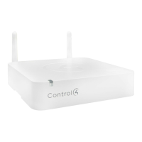
Covers Ethernet, WiFi, ZigBee, Z-Wave connectivity, security, and antennas.

Control and Connectivity Ports

Lists IR, Serial, Contact, and Relay ports with their voltage and current ratings.

Power and Environmental Specs

Outlines power requirements, consumption, operating/storage temperatures, and dimensions.

Front View Component Identification

Activity LED

Indicates controller audio streaming status.

IR Window

IR receiver for learning codes.

Caution LED

Shows boot process and factory restore status.

Link LED

Indicates controller identification and Director communication.

Power LED

Confirms AC power connection.

Back View Port Identification

Power and Network Ports

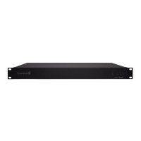
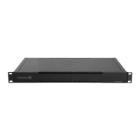
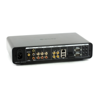
AC power input and Ethernet connection port.

Audio and Serial Ports

Digital/analog audio I/O and RS-232 serial ports.

IR, Zigbee, and Z-Wave Ports

IR emitter/serial jacks and antenna connectors.

USB and Control Ports

USB ports for storage/adapters and contact/relay terminal blocks.

Controller Installation Steps

Initial Network Setup

Ensure home network is ready before controller setup.

Physical Mounting

Mount controller in rack/shelf with ventilation.

Network Connection

Connect via Ethernet or configure for WiFi.

Device and System Connections

Connect devices, storage, and power up.

Rack Mounting and Rubber Feet

Rack Mount Installation

Use pre-installed rack ears for mounting; they can be reversed.

Attaching Rubber Feet

Remove rack ears, attach rubber feet using screws.

Pluggable Terminal Block Connections

Terminal Block Overview

Removable plastic connectors for secure wire connections.

Connecting a Device

Insert wires into block, tighten screws with a flat-blade screwdriver.

Contact Port Connections

Sensor with Power Connection

Connect motion sensors using +12V, SIG, and GND terminals.

Dry Contact Sensor Connection

Wire door sensors to COM, NC, or NO terminals.

Externally Powered Sensor Connection

Connect driveway sensors via +12V, SIG, and GND.

Relay Port Connections

Single Relay Device Connection

Connect fireplace control using COM, NC, or NO terminals.

Dual Relay Device Connection

Wire blinds using separate relay terminals.

Relay with Power Connection

Connect amplifier trigger using COM, NC, or NO terminals.

Serial Port Configuration and Use

Serial Port Capabilities

Supports DB9; ports 3/4 have flow control limitations.

Serial Cable and Pinout

Use 3.5mm-to-DB9 cable; refer to KB article for pinout.

Setting Serial Port Parameters

Configure serial settings via Composer Pro driver integration.

IR Emitter Setup

IR Emitter Connection

Connect IR emitters to available IR OUT ports.

IR Emitter Placement

Affix emitter to device's IR receiver.

External Storage Device Setup

Supported Storage Types

Use externally powered USB drives or solid-state USB drives.

Recommended Formatting

FAT32 format with a single primary partition is recommended.

Composer Pro Driver Integration

Troubleshooting Procedures

Factory Reset Process

Restore controller to default settings using the reset button.

Controller Power Cycling

Turn controller off/on by holding ID button.

Network Settings Reset

Reset network configurations by holding ID button during power-on.

LED Status Indicators

Additional Resources and Support

Important Safety Instructions

General Usage Precautions

Read, keep, heed warnings, follow all instructions, avoid water and heat.

Ventilation and Cleaning

Do not block ventilation; clean only with a dry cloth.

Accessory and Mounting Safety

Use manufacturer-specified accessories and exercise caution with carts.

Continued Safety and Servicing Guidelines

Servicing and Damage Handling

Refer all servicing to qualified personnel; handle damaged cords carefully.

Power Cord Protection

Protect power cords from being walked on or pinched.

Electrical Surge and Lightning Precautions

Unplug during storms; consider surge arrestors for AC power.

Power Disconnection and Circuit Breaker

Disconnect power via cord or breaker; ensure breaker accessibility.

Short-Circuit Protection

Ensure building's protection device is rated not greater than 20A.

Power Source, Grounding, Polarization Warning

General warning about power sources, grounding, and polarization.

Grounding and Outlet Safety

Proper Outlet Requirement

Use NEMA 5-15 grounded outlets; do not force plugs or alter cords.

Grounding for Connected Devices

Ensure rooftop devices like satellite dishes are also properly grounded.

Common Grounding Point

Bonding point for common ground connection with compatible wire gauge.

Installation Environment and Interference

Indoor Fixed Location Use

For indoor use only in fixed locations like telecom centers or computer rooms.

Electrical Interference

May interfere with other electronic equipment if placed in close proximity.

Cabinet Slot Safety

Do not insert objects into cabinet slots to avoid electrical shock or fire.

User Serviceability and Battery Safety

No User-Serviceable Parts

Do not remove covers; refer servicing to qualified personnel.

Battery Replacement Caution

Risk of explosion/injury if battery is incorrect type; follow disposal instructions.

PoE Network Environment

Connect only to PoE networks without external routing per IEC TR62101.

Optical Transceiver Specification

Use UL listed, Rated Laser Class I, 3.3 Vdc optical transceivers.

Electrical Safety and Compliance Labels

General Electrical Safety

Warning about exposure to rain or moisture; save instructions.

USA & Canada Compliance Statement

FCC Part 15, Subpart B statement for Class B digital device operation.

ISED Canada and FCC Intentional Emissions Compliance

Canada ISED Compliance

Statement on licence-exempt transmitters/receivers complying with CNR RSS(s).

FCC Part 15 Intentional Emissions

Compliance with FCC Part 15.203 & IC RSS-247 for antenna requirements.

5.15-5.25 GHz Band Restriction

Operations in this band are restricted to indoor usage only.

RF Exposure and European Compliance

RF Radiation Exposure Statement

Maintain 10cm distance between radiator and body for uncontrolled environments.

Europe Compliance CE Mark

CE conformity indicates compliance for EU member states and EFTA countries.

EU Country Codes and WLAN Usage

EU Member State Codes

List of country codes associated with EU compliance.

WLAN 5 GHz Usage Restrictions

5.15-5.35GHz band operations are restricted to indoor usage.

United Kingdom Compliance and Recycling

UK Compliance Logo

Indicates UK conformity with relevant directives.

WEEE Compliance

Snap One's commitment to Waste Electrical and Electronic Equipment directive.

Australia & New Zealand Compliance

Document Information

Related product manuals